Dialogic
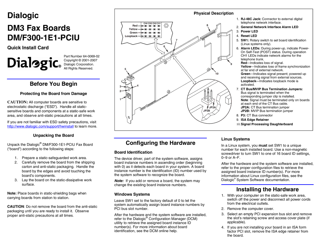
Physical Description
DM3 Fax Boards DM/F300-1E1-PCIU
Quick Install Card
Part Number
Copyright ©
Dialogic Corporation.
All Rights Reserved.
Before You Begin
Protecting the Board from Damage
CAUTION: All computer boards are sensitive to electrostatic discharge (“ESD”). Handle all static- sensitive boards and components at a
If you are not familiar with ESD safety precautions, visit http://www.dialogic.com/support/hwinstall to learn more.
Unpacking the Board
Red
Yellow
Green
Loopback
5
3![]() 4
4
2![]()
1
CH4 CH3 CH2 CH1
|
| 1. | |
| 8 |
| telephone network interface. |
| 2. | General Network Interface Alarm LED | |
|
| ||
|
| 3. | Power LED |
|
| 4. | Reset LED |
7 |
| 5. | SW1: Rotary switch to set board identification |
|
|
| (Linux systems only). |
6
6. Alarm LEDs: During
9
10
7.CT Bus/MVIP Bus Termination Jumpers:
| Bus signal is terminated when the |
| corresponding jumper clip is installed. |
| Note: Signal must be terminated only on boards |
| at each end of the CT Bus cable. |
JP2A | JP2A: CT Bus termination jumper |
JP2B | JP2B: MVIP Bus termination jumper |
8. | P3: CT Bus connector |
9. | ISA Edge Retainer |
10. Signal Processing Daughterboard
Unpack the Dialogic®
1.Prepare a
2.Carefully remove the board from the shipping carton and
3.Lay the board on the
Configuring the Hardware
Board Identification
The device driver, part of the system software, assigns board instance numbers in ascending order (beginning with 0) as it detects each board in your system. A board instance number is the identification (ID) number used by the system software to recognize the board.
Note: If you add or remove a board, the system may change the existing board instance numbers.
Linux Systems
In a Linux system, you must set SW1 to a unique number for each installed board. Use a
After the hardware and the system software are installed, refer to the proper configuration files to retrieve the assigned board instance ID number(s). For more information about Linux configuration files, see the Dialogic® System Software documentation.
Note: Place boards in
CAUTION: Do not remove the board from the
Windows Systems
Leave SW1 set to the factory default of 0 to let the system automatically assign board instance numbers by PCI bus slot number.
After the hardware and the system software are installed, refer to the Dialogic® Configuration Manager (DCM) utility to retrieve the assigned board instance ID number(s). For more information about board identification, see the DCM online help.
Installing the Hardware
1.With your computer on the
2.Remove the computer cover.
3.Select an empty PCI expansion bus slot and remove the slot’s retaining screw and access cover plate (if applicable).
4.If you are not installing your board in an ISA form factor PCI slot, remove the ISA edge retainer from the board.