sc100TM specifications
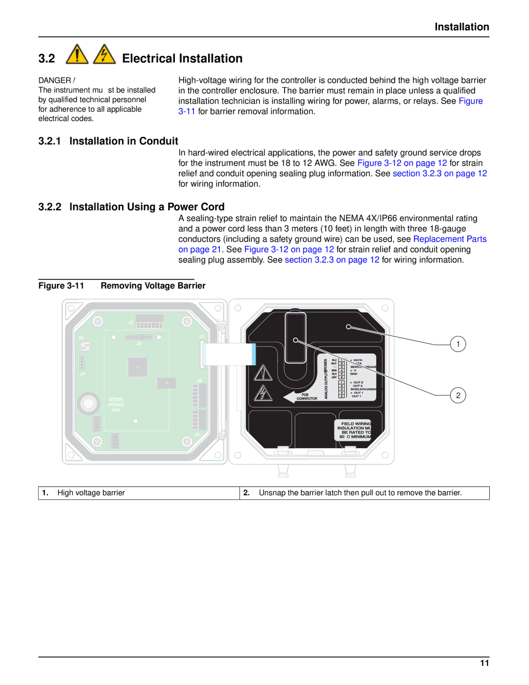
The Hach sc100TM is a versatile and reliable device designed for monitoring and controlling water quality in various applications. Its robust features make it an essential tool for environmental scientists, water treatment facilities, and industrial processes. The sc100TM is equipped with a user-friendly interface that allows for easy navigation and configuration, ensuring quick implementation in various settings.One of the standout features of the sc100TM is its multi-parameter capability. This device is designed to monitor a range of water quality parameters, including pH, dissolved oxygen, turbidity, and temperature, among others. This flexibility allows users to conduct comprehensive water quality assessments without the need for multiple devices, thereby reducing costs and maximizing efficiency.
The sc100TM employs advanced digital sensor technology that ensures high accuracy and reliability in readings. These sensors are designed to provide consistent performance even in challenging environments. The device is also compatible with a wide range of Hach sensors, enabling users to customize their monitoring solutions based on specific requirements.
In addition to its measurement capabilities, the sc100TM features built-in data logging and reporting functions. This allows users to track water quality trends over time, facilitating informed decision-making and compliance with regulatory standards. The data can be easily exported for further analysis or reporting, making it an essential companion for environmental monitoring and compliance activities.
Connectivity is another critical aspect of the sc100TM. With options for wireless data transmission, users can access real-time data remotely, promoting better monitoring and quicker response to any changes in water quality. This feature is particularly beneficial for facilities that require constant monitoring, as it enables quick interventions when necessary.
Another significant advantage of the sc100TM is its durability and design. Constructed to withstand harsh operating conditions, the device is both weatherproof and suitable for various industrial environments. Its compact design also allows for easy installation in tight spaces, making it adaptable to different setups.
In summary, the Hach sc100TM sets itself apart as a powerful tool for water quality monitoring. With its multi-parameter capabilities, advanced sensor technology, comprehensive data logging, and connectivity features, it provides users with the capability to maintain compliance and enhance water quality management strategies effectively. Whether in a laboratory or a field setting, the sc100TM is designed to meet the demands of modern water quality monitoring.

