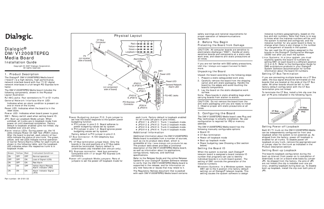
Physical Layout
safety warnings and national requirements for proper operation of telecommunications equipment.
instance numbers geographically, based on the bus and slot numbers. Note that there is no way to know what the instance numbers will be until
Dialogic®
DM/V1200BTEPEQ
Media Board
Installation Guide
Copyright © 2007 Dialogic Corporation.
All rights reserved.
1. Product Description
The Dialogic® DM/V1200BTEPEQ Media board (“board”) is a
CT Bus
Connector
P5
(on reverse side of board)
4 3 2 1
Red
Yellow
Green
Loopback
Alarm/Status
LEDs
Pins 321
JP5 | SW1 | |
Power LED | ||
|
2. Before You Begin
Protecting the Board from Damage
CAUTION: All computer boards are sensitive to electrostatic discharge (“ESD”). Handle all static- sensitive boards and components at a
If you are not familiar with ESD safety precautions,
visit http://dialogic.com/support/hwinstall to learn
more.
Unpacking the Board
Unpack the board according to the following steps:
1. | Prepare a |
2. | Carefully remove the board from the shipping |
the system is started and configured, and the instance number for any given board is likely to change when there is any change in the number or arrangement of boards in the system.
You can read the ID numbers assigned to the boards in the Dialogic® Configuration Manager (DCM) tool after you start the system.
Linux Systems: In a Linux system, you must explicitly specify the board ID numbers by setting SW1 on each board to a different position
Setting CT Bus Termination
If you are connecting multiple boards via a CT Bus cable, the bus signal should be terminated on the
network interface board with four T1/E1 digital network interfaces in a
The DM/V1200BTEPEQ Media board includes the following components, shown in the Physical Layout illustration:
General Network Interface Alarm LED:
Indicates when an alarm condition is present on one or more of the trunks.
Reset LED: Indicates when the board is in the reset state.
Power LED: Indicates when board power is good.
P10
(on component side of board)
JP4X12 | 2 | ||
& JP3X12 | |||
1 | |||
|
| ||
| JP4X11 |
| |
| & JP3X11 |
| |
JP4X13 |
| 3 | |
| 4 | ||
& JP3X13 | |||
PCI Express |
|
| |
Connector | JP3X14 |
| |
|
| ||
| & JP4X14 |
| |
1
2
3
4
Reset LED
General Network
Alarm LED
carton and |
board by the edges and avoid touching the |
board's components. |
3. Lay the board on the |
surface. |
Note: Place boards in
CAUTION: Do not remove the board from the
3. Configuring the Board
boards that are located at the ends of the CT Bus cable. All other boards should be left in their factory default configuration with the CT Bus termination pins not linked.
To terminate the CT Bus, install a link clip over the pair of P5 pins indicated in the following figure.
CT Bus
Termination
CT Bus ![]() Pins
Pins
Connector
SW1: Rotary switch used when setting board ID.
JP5:
Alarm/status LEDs: During
Green | Yellow | Red | Indicated Condition |
|
|
|
|
ON | OFF | OFF | Normal operation |
|
|
|
|
OFF | OFF | ON | Loss of Signal (LOS) |
|
|
|
|
ON | OFF | ON | Red Alarm |
|
|
|
|
ON | ON | OFF | Yellow Alarm/Remote |
|
|
| Alarm Indicator (RAI) |
|
|
|
|
ON | ON | ON | Alarm Indicator Signal |
|
|
| (AIS) |
|
|
|
|
Power Budgeting Jumper P10:
■P10 jumper in pins
■P10 jumper in pins
Factory default is P10 jumper in pins
CT Bus Connector: H.100 telephony bus connector.
P5: CT Bus termination jumper block. Only the boards in the end positions of a CT Bus cable should be terminated. Factory default is unterminated (clip installed over one pin only).
PCI Express connector: Host bus connector. Compatible with x1 or larger PCI Express Link connectors.
each trunk. Factory default is loopback enabled for all trunks (all pairs of pins linked).
■JP3X11 & JP4X11: Trunk 1 loopback mode.
■JP3X12 & JP4X12: Trunk 2 loopback mode.
■JP3X13 & JP4X13: Trunk 3 loopback mode.
■JP3X14 & JP4X14: Trunk 4 loopback mode.
Additional Information
Additional information about the DM/V1200BTEPEQ Media board is available from a number of sources, such as via its product data sheet, which is
accessible at http://www.dialogic.com/products/list.asp. The product data sheet provides a functional description of the DM/V1200BTEPEQ Media board, as well as information about its applications, configurations, features, and technical specifications.
Refer to the Release Guide and the online Release Update for your Dialogic® System Software release to verify that the DM/V1200BTEPEQ Media board is supported in the release, and for information on any new features or issues that may relate to it.
The Regulatory Notices document that is packed with each DM/V1200BTEPEQ Media board contains
The DM/V1200BTEPEQ Media board uses Plug and Play technology to simplify installation. No user configuration is required for IRQ or memory address.
The DM/V1200BTEPEQ Media board has the following manually configurable options:
■Board ID
■CT Bus termination
■
■
■Power budgeting (see Choosing a Slot section below)
Setting the Board ID
When the system is started, each Dialogic® telecom board is assigned a board instance ID number that programs can use to identify individual boards in a
Windows Systems: In a Windows system, leave SW1 set to the 0 position (the factory default setting) on all Dialogic® telecom boards. This setting causes the system software to assign
Setting Power-off Loopback
Each E1/T1 trunk on the DM/V1200BTEPEQ Media can be independently configured for front end loopback when the system is not powered up. As shipped from the factory,
Setting Boot-up Loopback
The board’s loopback configuration during the
Part number: