Dialogic®
Station Interface Box
SI/240
Part Number
Copyright ©
Dialogic Corporation.
All Rights Reserved.
1. Protecting the Board from Damage
![]() Caution! All computer boards are sensitive to electrostatic discharge (“ESD”). Handle all static- sensitive boards and components at a
Caution! All computer boards are sensitive to electrostatic discharge (“ESD”). Handle all static- sensitive boards and components at a
If you are not familiar with ESD safety precautions, visit http://www.dialogic.com/support/hwinstall to learn more.
Unpacking the Board
Unpack the Dialogic® Station Interface Box (“SIB”) according to the following steps:
1.Prepare a
2.Carefully remove the SIB from the shipping carton and
3.Lay the SIB on the
Note: Place the SIB in
CAUTION: Do not remove the SIB from the
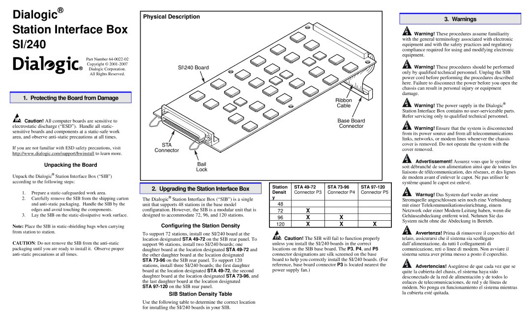
Physical Description
SI\240 Board
STA
Connector
Bail
Lock
2. Upgrading the Station Interface Box
The Dialogic® Station Interface Box (“SIB”) is a single unit that supports 48 stations in the base model configuration. However, the SIB is a modular unit that is designed to accommodate 72, 96, and 120 stations.
Configuring the Station Density
To support 72 stations, install one SI/240 board at the location designated STA
STA
SIB Station Density Table
Use the following table to determine the correct location for installing the SI/240 boards in your SIB.
Ribbon
Cable
Base Board
Connector
Station | STA | STA | STA |
Densit | Connector P3 | Connector P4 | Connector P5 |
y |
|
|
|
48 |
|
|
|
72 | X |
|
|
96 | X | X |
|
120 | X | X | X |
![]() Caution! The SIB will fail to function properly unless you install the SI/240 boards in the correct locations on the SIB base board. The P3, P4, and P5 connector designations are silk screened on the base board to help you correctly install the SI/240 boards. (For reference, base board connector P3 is located nearest the power supply fan.)
Caution! The SIB will fail to function properly unless you install the SI/240 boards in the correct locations on the SIB base board. The P3, P4, and P5 connector designations are silk screened on the base board to help you correctly install the SI/240 boards. (For reference, base board connector P3 is located nearest the power supply fan.)
3. Warnings
![]() Warning! These procedures assume familiarity with the general terminology associated with electronic equipment and with the safety practices and regulatory compliance required for using and modifying electronic equipment.
Warning! These procedures assume familiarity with the general terminology associated with electronic equipment and with the safety practices and regulatory compliance required for using and modifying electronic equipment.
![]() Warning! These procedures should be performed only by qualified technical personnel. Unplug the SIB power cord before performing the procedures described here. Failure to disconnect the power before you open the chassis can result in personal injury or equipment damage.
Warning! These procedures should be performed only by qualified technical personnel. Unplug the SIB power cord before performing the procedures described here. Failure to disconnect the power before you open the chassis can result in personal injury or equipment damage.
![]() Warning! The power supply in the Dialogic® Station Interface Box contains no
Warning! The power supply in the Dialogic® Station Interface Box contains no
![]() Warning! Ensure that the system is disconnected from its power source and from all telecommunications links, networks, or modem lines whenever the chassis cover is removed. Do not operate the system with the cover removed.
Warning! Ensure that the system is disconnected from its power source and from all telecommunications links, networks, or modem lines whenever the chassis cover is removed. Do not operate the system with the cover removed.
![]() Advertissement! Assurez vous que le système soit débranché de son alimentation ainsi que de toutes les liaisons de télécommunication, des réseaux, et des lignes de modem avant d’enlever le capot. Ne pas utiliser le système quand le capot est enlevé.
Advertissement! Assurez vous que le système soit débranché de son alimentation ainsi que de toutes les liaisons de télécommunication, des réseaux, et des lignes de modem avant d’enlever le capot. Ne pas utiliser le système quand le capot est enlevé.
![]() Warnug! Das System darf weder an eine Stromquelle angeschlossen sein noch eine Verbindung mit einer Telekommunikationseinrichtung, einem Netzwerk oder einer
Warnug! Das System darf weder an eine Stromquelle angeschlossen sein noch eine Verbindung mit einer Telekommunikationseinrichtung, einem Netzwerk oder einer
![]() Avvertenza! Prima di rimuovere il coperchio del telaio, assicurarsi che il sistema sia scollegato dall’alimentazione, da tutti I collegamenti di comunicazione, reti o linee di modem. Non avviare il sistema senza aver prima messo a posto il coperchio.
Avvertenza! Prima di rimuovere il coperchio del telaio, assicurarsi che il sistema sia scollegato dall’alimentazione, da tutti I collegamenti di comunicazione, reti o linee di modem. Non avviare il sistema senza aver prima messo a posto il coperchio.
![]() Advertencias! Asegúrese de que cada vez que se quite la cubierta del chasis, el sistema haya sido desconectado de la red de alimentación y de todos lo enlaces de telecomunicaciones, de red y de líneas de módem. No ponga en funcionamiento el sistema mientras la cubierta esté quitada.
Advertencias! Asegúrese de que cada vez que se quite la cubierta del chasis, el sistema haya sido desconectado de la red de alimentación y de todos lo enlaces de telecomunicaciones, de red y de líneas de módem. No ponga en funcionamiento el sistema mientras la cubierta esté quitada.