Installing the EtherLite Hardware
1.Write the MAC address of the EtherLite module on the following line. It will be needed during software installation. This address is printed on a label next to the power plug at the back of the unit.
MAC Address # 00AOE7______________
2.Connect the Ethernet cable to the unit using the
Rack Mount Considerations
When doing a rack mount installation consider the following:
• Cumulative power requirements of the unit and other equipment |
installed in the rack. Do not overload rack supply circuits. |
• Safety and stability. Always stack the rack from bottom up to ensure |
a stable and safe rack. |
Note: The EtherLite 32 weighs 5.8 lbs (2.6 kgs). |
• Air flow in the rack. Make sure the unit’s ambient temperature does |
not exceed 95°F (35°C). |
• Grounding. Earth ground the unit reliably to the rack system. The |
earth ground connection must be maintained when the supply con- |
EtherLite | Signal | |||
|
|
| ||
1 | RTS (out) | 4 | 7 | |
2 | DSR (in) | 6 | 6 | |
3 | DCD (in) | 8 | 1 | |
|
|
|
| |
4 | RxD (in) | 3 | 2 | |
5 | TxD (out) | 2 | 3 | |
6 | GND | 7 | 5 | |
|
|
|
| |
7 | DTR (out) | 20 | 4 | |
8 | CTS (in) | 5 | 8 |
RJ-45 Pinouts
Pin to Pin
1 to 1
2 to 2
3 to 3
4 to 4
5 to 5
6 to 6
7 to 7
8 to 8
Crossover
Pin to Pin
1 to 3
2 to 6
3 to 1
4 to 4
5 to 5
6 to 2
7 to 7
8 to 8
Pin 1 | Pin x | |
|
|
|
|
|
|
|
|
|
|
|
|
|
|
|
|
|
|
|
|
|
|
|
|
nection is other than a direct connection to the branch circuit. |
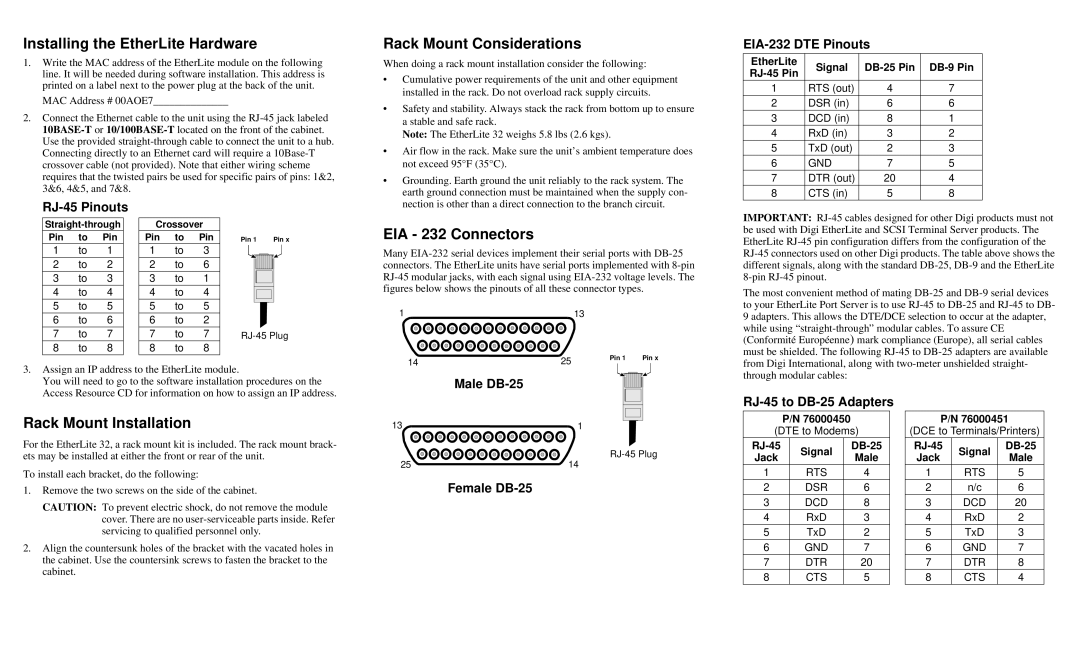
EIA - 232 Connectors
Many
1 |
| 13 |
| |
14 | 25 |
| Pin 1 | Pin x |
| ||||
| ||||
|
|
| ||
IMPORTANT:
The most convenient method of mating
3.Assign an IP address to the EtherLite module.
You will need to go to the software installation procedures on the Access Resource CD for information on how to assign an IP address.
Male
through modular cables:
Rack Mount Installation
For the EtherLite 32, a rack mount kit is included. The rack mount brack- ets may be installed at either the front or rear of the unit.
To install each bracket, do the following:
1.Remove the two screws on the side of the cabinet.
CAUTION: To prevent electric shock, do not remove the module cover. There are no
2.Align the countersunk holes of the bracket with the vacated holes in the cabinet. Use the countersink screws to fasten the bracket to the cabinet.
13 ![]()
![]() 1
1
25 |
| 14 |
|
Female DB-25
RJ-45 to DB-25 Adapters
P/N 76000450
(DTE to Modems)
Signal | |||
Jack | Male | ||
| |||
1 | RTS | 4 | |
2 | DSR | 6 | |
|
|
| |
3 | DCD | 8 | |
4 | RxD | 3 | |
5 | TxD | 2 | |
|
|
| |
6 | GND | 7 | |
7 | DTR | 20 | |
8 | CTS | 5 | |
|
|
|
P/N 76000451
(DCE to Terminals/Printers)
Signal | |||
Jack | Male | ||
| |||
1 | RTS | 5 | |
2 | n/c | 6 | |
|
|
| |
3 | DCD | 20 | |
4 | RxD | 2 | |
5 | TxD | 3 | |
|
|
| |
6 | GND | 7 | |
7 | DTR | 8 | |
8 | CTS | 4 | |
|
|
|