
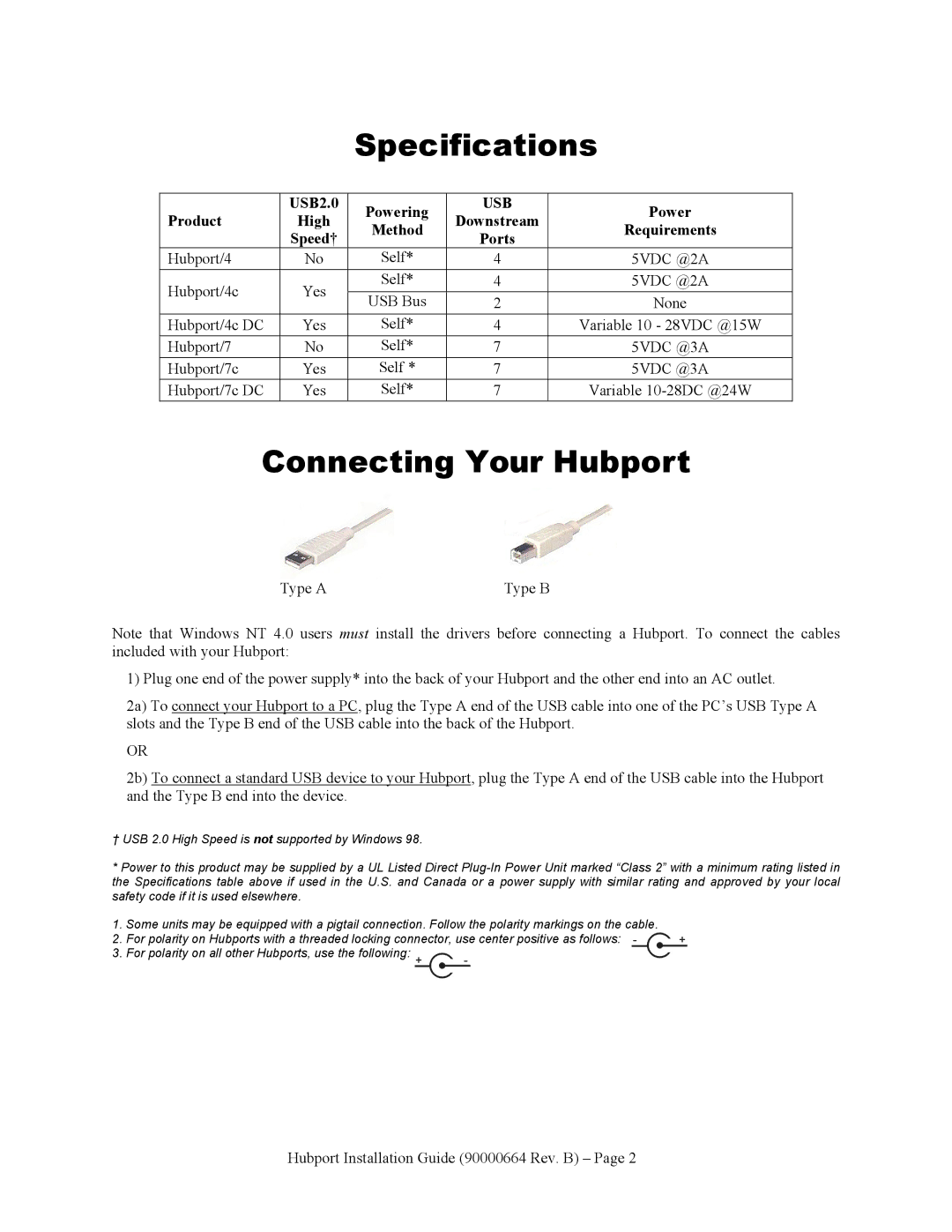
Hubport/7c DC, Hubport/7c, Hubport/4, Hubport/4c DC, Hubport/4c specifications
Digi Hubport series, including models such as Hubport/4c DC, Hubport/7, Hubport/4c, and Hubport/7c is a groundbreaking family of modular connectivity solutions designed for demanding industrial and commercial environments. These devices are engineered to enhance data transmission and connectivity, catering specifically to applications that require high reliability and performance.One of the standout features of the Digi Hubport models is their ability to support multiple devices simultaneously through a single connection. Hubport/4c DC, for instance, can seamlessly connect four devices, while Hubport/7 and Hubport/7c offer connections for seven devices. This modular approach allows for greater flexibility and scalability in network design, accommodating various device types and configurations without needing additional infrastructure.
In terms of technology, the Hubport series employs advanced USB technology for high-speed data transfer, ensuring that all connected devices operate efficiently and effectively. The integration of USB 3.0 in models like Hubport/7c enhances the data transfer rates, making it particularly suitable for environments requiring rapid data access and processing, such as data centers and manufacturing facilities.
The Hubport series also boasts enhanced power management capabilities. Model Hubport/4c DC features dual power supply options, ensuring uninterrupted operation even during power fluctuations. This characteristic is crucial for industrial applications where downtime can result in significant financial losses.
Another notable aspect of the Digi Hubport series is its rugged design. Built to withstand harsh environmental conditions, these hubs are often equipped with protective enclosures that ensure durability and longevity. This resilience makes them ideal for use in factories, warehouses, and outdoor settings where traditional electronics may fail.
Additionally, the Digi Hubport devices support plug-and-play functionality, simplifying installation and reducing the time required to set up new systems. Users can easily connect devices without the need for extensive technical knowledge or complex installation processes.
Security is also a critical consideration in the Digi Hubport design. These devices include features that protect against unauthorized access and data breaches, ensuring that sensitive information remains secure throughout its transmission and processing.
In summary, the Digi Hubport series, encompassing Hubport/4c DC, Hubport/7, Hubport/4c, and Hubport/7c, provides a robust and flexible connectivity solution tailored to meet the needs of diverse environments. With high-speed data transfer, modular connectivity, rugged durability, and comprehensive security features, these devices are set to revolutionize the way industries approach connectivity and data management.