Digi MIL-190C manual Introduction, Installation, Diagnostic LEDs and Conditions Indicated

Models: MIL-190C

1 4
Download 4 pages 33.7 Kb
Page 2
Image 2
Introduction

Install Guide

Introduction

The MIL-190C supports Fast Ethernet in both half- and full-duplex mode. For network budget constraint, the MIL-190C uses 150 nanoseconds (approximately 30 meters of cable) during conversion in each direction.

To maximize the fiber cable distance, use one meter of category 5 (CAT 5) UTP cable when connecting directly to a node (subject to fiber budget of 16 dBm and collision domain restrictions). In full-duplex environments, up to 100 m of CAT 5 UTP and 15Km of 1300 nm single-mode fiber cable can be used:

Launch power: -15dB

Receive sensitivity: -31dB.

Installation

1.Attach a UTP cable from the network to the RJ-45 port. (Use screened UTP cabling for CISPR 22 class B installation.)

2.Cross-connect the fiber cables: Attach both fiber cables TX to RX and RX to TX from the fiber network cabling to the SC-type connector on the MIL-190C.

3.Apply power to the unit:

a.Insert the power adapter's receptacle into the power plug.

b.Insert the power adapter into a wall outlet.

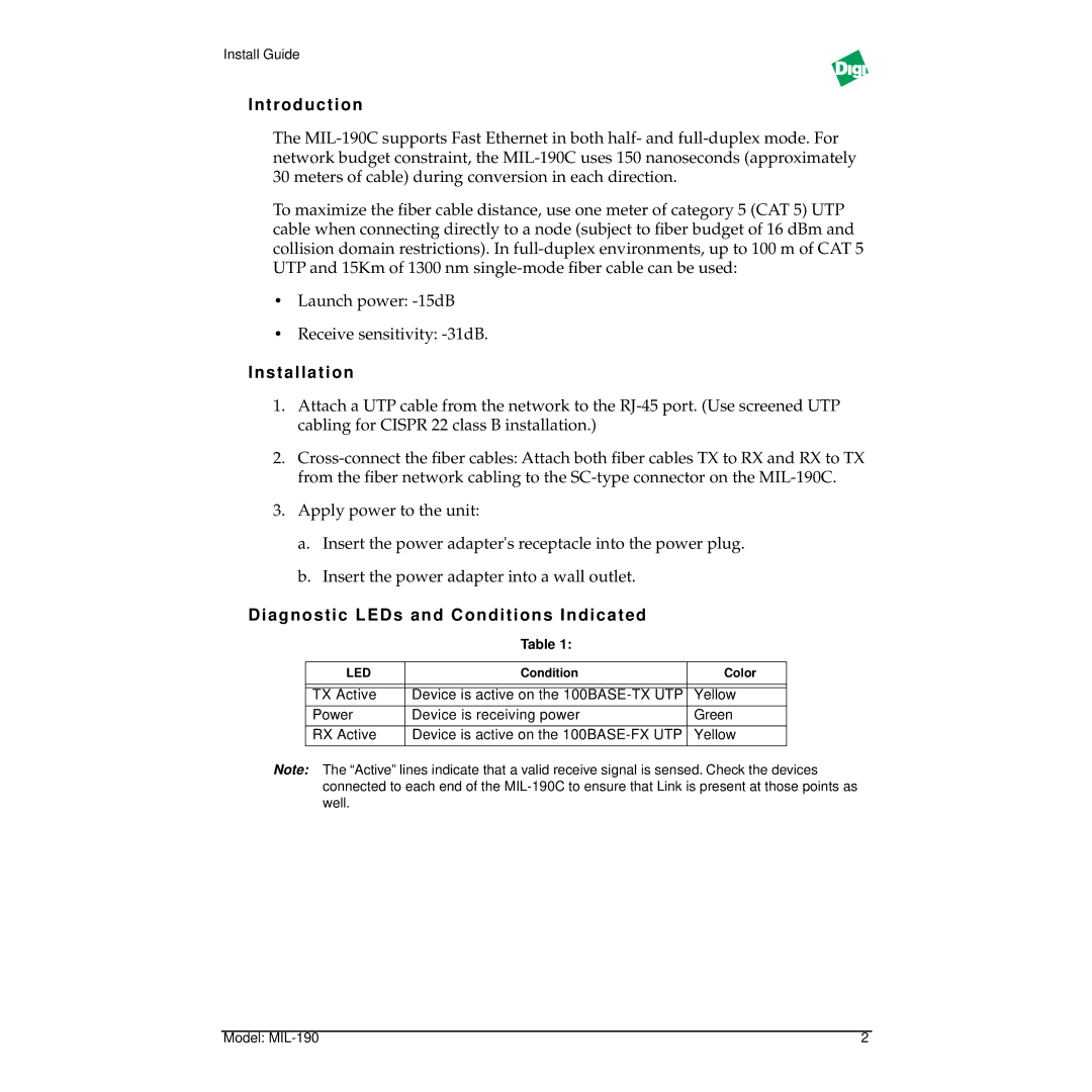
Diagnostic LEDs and Conditions Indicated

Table 1:

LED

Condition

Color


TX Active

Device is active on the 100BASE-TX UTP

Yellow

Power

Device is receiving power

Green


RX Active

Device is active on the 100BASE-FX UTP

Yellow


Note: The “Active” lines indicate that a valid receive signal is sensed. Check the devices connected to each end of the MIL-190C to ensure that Link is present at those points as well.

Model: MIL-190

2

Page 2
Image 2
Digi MIL-190C manual Introduction, Installation, Diagnostic LEDs and Conditions Indicated