IMPORTANT SAFETYADVICE
READ THESE INSTRUCTIONS BEFORE USE.
DO NOT use the heater on deep pile carpets or the long hair type of rugs, or less than 750mm (30") away from any overhanging surface. Keep combustible materials such as drapes and other furnishings clear from the front, sides and rear of the heater. Do not use heater to dry your laundry.
DO NOT use the heater in the immediate surroundings of a bath, a shower or a swimming pool.
DO NOT place the heater directly below a fixed socket outlet. The socket-outlet must be accessible at all times to enable the mains plug to be disconnected as quickly as possible.
DO NOT COVER or obstruct the air inlet and outlet openings in any way.
The heater must be on a flat stable surface when in use.
DO NOT operate the heater with the mains lead overhanging the front outlet grille.
NEVER leave the heater unattended when it is used by or near the aged, infirm person’s or children.
If you use this heater in conjunction with an external thermal control, a programme controller, a timer or any other device which switches on the heater automatically, observe all safety warnings AT ALL TIMES since a fire risk exists when the heater is accidentally covered or displaced.
The heater carries the Warning symbol | indicating that |
it must not be covered. | |
The instruction leaflet belongs to the appliance and must be kept in a safe place. If changing owners, the leaflet must be surrendered to the new owner.
IMPORTANT – If the mains lead of this appliance is damaged, it must be replaced by the manufacturer or its service agent or a similarly qualified person in order to avoid a hazard.
Electrical connection
This heater must be used on an A.C.~ supply only and the voltage marked on the heater must correspond to the supply voltage. This heater is fitted with a plug incorporating a 13 amp fuse. When replacing the fuse, a 13 amp fuse approved by ASTA to BS 1362 must be used.
If the plug is not suitable for the socket outlets in your home, the plug must be cut off and an appropriate one fitted. A plug cut off from a mains lead will give a shock hazard if inserted into a 13 amp socket elsewhere in the house. To avoid this, it should be disposed of immediately.
NOTE: The fuse cover of a non-rewirable plug must be refitted when changing the fuse. Should the cover become lost, the plug must not be used until the correct replacement fuse cover is obtained from your supplier or by contacting our customer helpline.
IMPORTANT : The wires in this mains lead are coloured in accordance with the following code :
BLUE :NEUTRAL
BROWN :LIVE
As the colours of the wires in the mains lead may not correspond with the coloured markings in your plug, proceed as follows :
Connect the BROWN wire to the terminal marked ‘L’ or coloured RED. Connect the BLUE wire to the terminal marked ‘N’ or coloured BLACK. Note : ‘L’ or ‘N’ must not be connected to the EARTH terminal marked
‘E’ or  or coloured GREEN or GREEN AND YELLOW. If in doubt, consult your electrician.
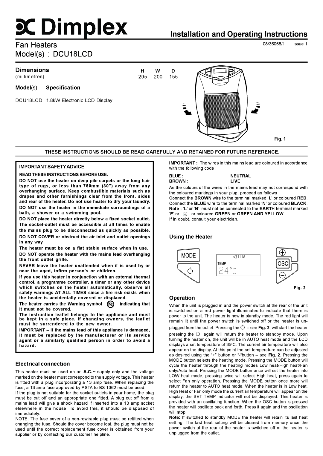
Using the Heater
Fig. 2
Operation
When the unit is plugged in and the power switch at the rear of the unit is switched on a red power light illuminates to indicate that there is power to the unit. The heater is now in standby mode. The red light will remain lit until the power switch is switched off or the heater is un-
plugged from the outlet. Pressing the  – see Fig. 2, will start the heater
pressing the  again will return the heater to standby mode. Upon turning the heater on, the unit will be in AUTO heat mode and the LCD displays a set temperature of 350C. The current air temperature will also appear on the display. At this point the set temperature can be adjusted as desired using the “+” button or “-“button – see Fig. 2. Pressing the MODE button selects the heating mode. Pressing the MODE button will cycle the heater through the heating modes Low heat/High heat/Fan only/Auto heat. Pressing the MODE button once will set the heater into LOW heat mode, pressing twice will select High heat, press again to select Fan only operation. Pressing the MODE button once more will return the heater to AUTO heat mode. When the heater is in Low heat, High Heat or Fan only mode the current air temperature will appear on the display, the SET TEMP indicator will not be displayed. This heater is provided with an oscillating function. When the OSC button is pressed the heater will oscillate back and forth. Press it again and the oscillation will stop.
Note: If switched to standby MODE the heater will retain its last heat setting. The last heat setting will be cleared from memory once the power switch at the rear of the heater is switched off or the heater is unplugged from the outlet.