APPENDIX: 12.5 HYDRAULIC BLOCK DIAGRAM
Hydraulic Block Diagram
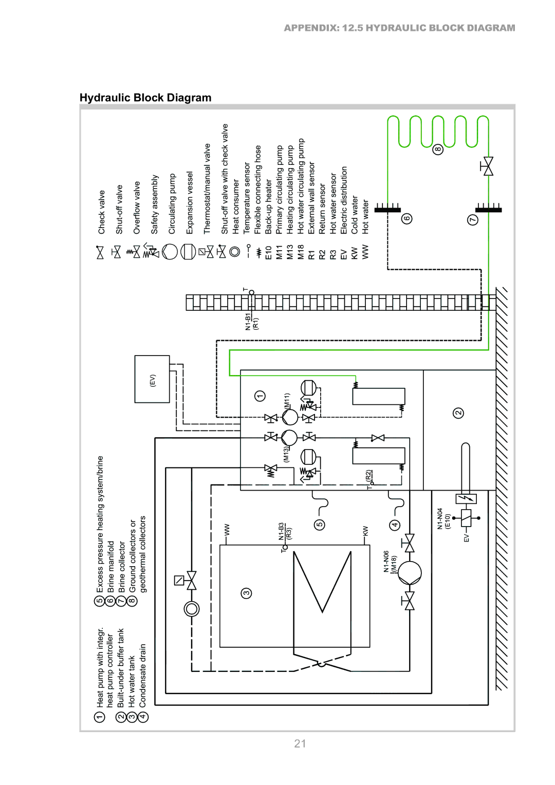
Checkvalve |
| Overflowvalve | Safetyassembly | Circulatingpump | Expansionvessel | Thermostat/manualvalve | Heatconsumer | Temperaturesensor | Flexibleconnectinghose | Primarycirculatingpump | Heatingcirculatingpump | Hotwatercirculatingpump | Externalwallsensor | Returnsensor | Hotwatersensor | Electricdistribution | Coldwater | Hotwater | ||||
Excesspressureheatingsystem/brine | Brinemanifold | Brinecollector | Groundcollectorsor | geothermalcollectors |
|
|
|
|
|
|
|
|
|
|
|
|
|
|
|
|
|
|
Heatpumpwithintegr. | heatpumpcontroller | Hotwatertank | Condensatedrain |
|
|
|
|
|
|
|
|
|
|
|
|
|
|
|
|
|
| |
|
|
|
|
|
|
|
|
|
|
|
|
|
|
|
| 21 |
|
|
|
|
|
|