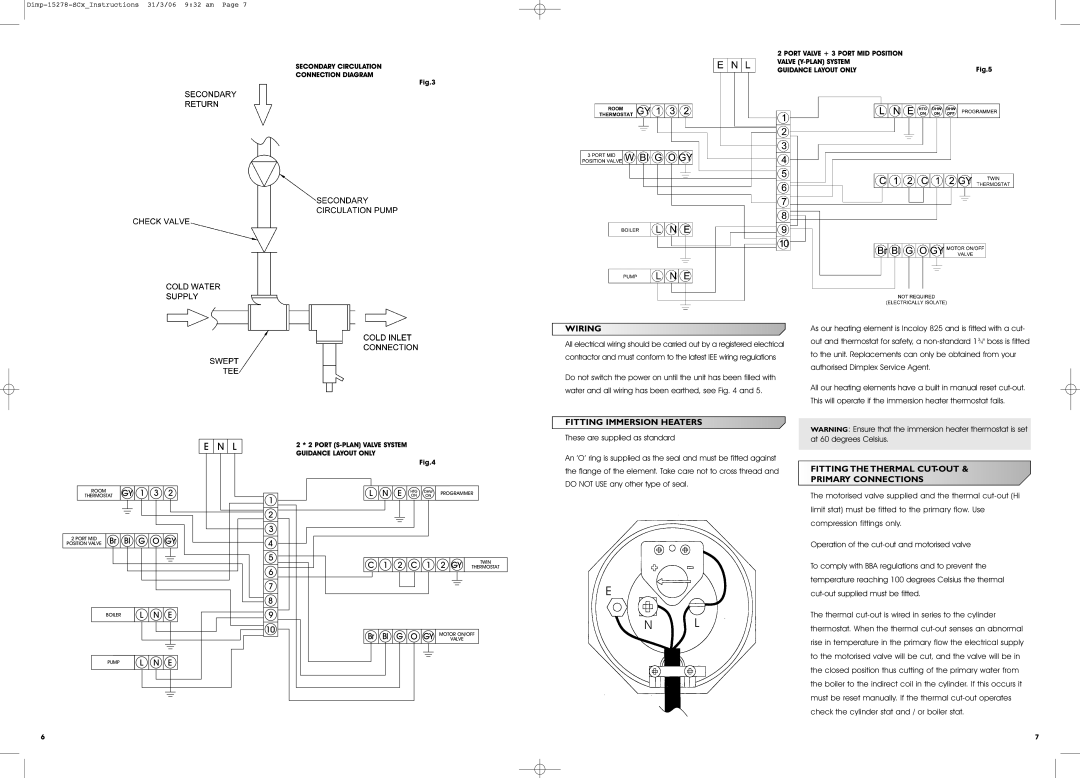
Unvented Water Heater specifications
The Dimplex Unvented Water Heater is a cutting-edge solution for modern water heating needs, providing efficient and reliable hot water without the complications of traditional tank systems. This innovative device is designed to deliver a continuous supply of hot water, catering to domestic and commercial applications alike.One of the standout features of the Dimplex Unvented Water Heater is its capacity to store and deliver hot water at high pressures. This means users can enjoy powerful showers and effective taps without the fluctuations often experienced with older systems. The heater is available in various capacities, allowing it to be tailored to meet the specific hot water demands of any household or facility.
The technology behind the Dimplex Unvented Water Heater includes a highly efficient heating element, which ensures quick recovery times and lower energy consumption. With advanced insulation techniques, the heater minimizes heat loss, thus enhancing overall efficiency. This not only helps to reduce energy bills but also contributes to a more environmentally friendly solution.
Safety is a top priority in the design of the Dimplex Unvented Water Heater. It features built-in safety systems, such as pressure relief valves and thermal cut-outs, to protect against overheating and excessive pressure, ensuring peace of mind for users. Additionally, the unit is easy to install, favoring a compact design that can fit into various settings, making it suitable for both new installations and retrofitting to existing systems.
Another characteristic worth noting is the user-friendly interface. The Dimplex Unvented Water Heater often includes an onboard control panel, allowing users to set and monitor temperatures easily. Some models may come with smart technology integration, enabling remote operation and management through mobile devices.
Maintenance is also simplified with the Dimplex Unvented Water Heater, as it is designed for easy access to components when servicing is required. This helps ensure longevity and optimal performance over time.
In summary, the Dimplex Unvented Water Heater stands out for its efficiency, safety features, and advanced technology, making it a smart choice for anyone looking to upgrade their hot water system. Robust, reliable, and designed with user convenience in mind, this water heater meets the demands of contemporary lifestyles seamlessly.

