
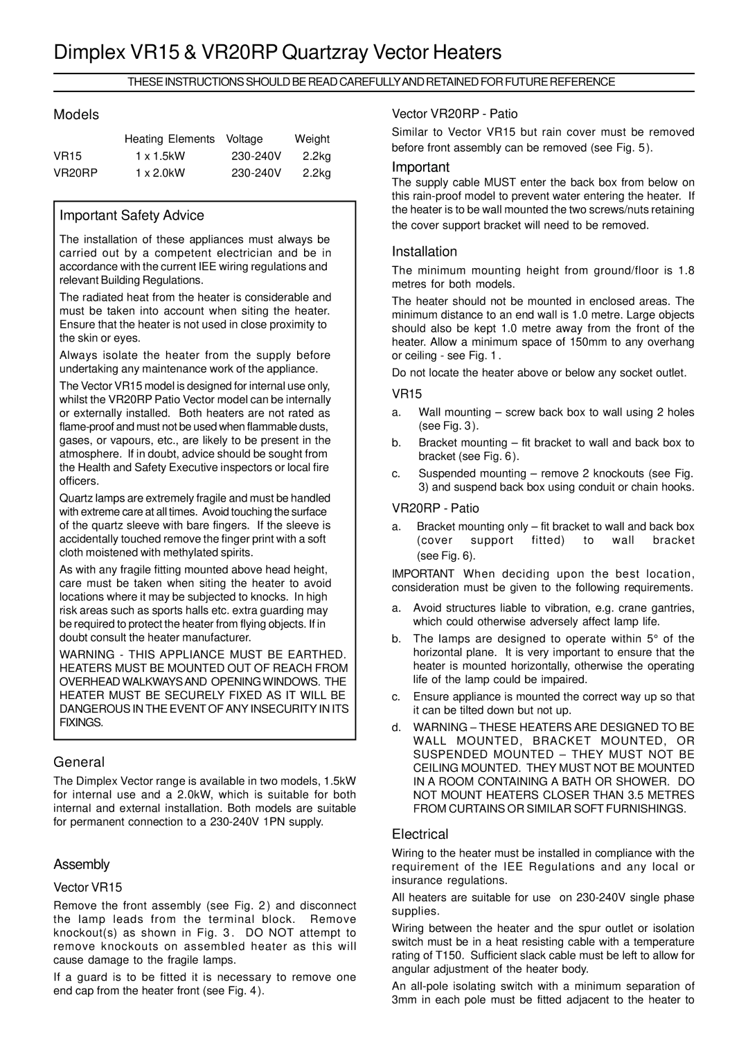
VR20RP, VR15 specifications
Dimplex, a renowned name in the world of electric heating solutions, offers an impressive range of products tailored to meet modern heating demands. Among their noteworthy offerings are the Dimplex VR20RP and VR15 electric radiators, both designed to deliver efficient heat while incorporating innovative technologies and user-friendly features.The Dimplex VR20RP model stands out with its sleek, contemporary design, making it an attractive addition to any living space. One of its main features is the advanced heating technology that utilizes dry thermal storage. This allows the radiator to store heat during off-peak hours, providing a cost-effective solution for homeowners looking to save on energy bills. The VR20RP has an impressive heat output, establishing comfortable temperatures quickly, ensuring you stay warm even during the coldest months.
On the other hand, the Dimplex VR15 model shares many features with its sibling but is tailored for smaller spaces. Both models utilize Dimplex's patented Smart Response technology, which adapts to the heating needs of the home environment. This smart feature learns your heating preferences and schedules, ensuring optimal comfort while minimizing energy consumption.
Another characteristic worth noting about both units is their built-in programmable timer. This feature allows users to set heating schedules according to their routines, enhancing energy efficiency further. Additionally, the radiators come equipped with a user-friendly digital display and intuitive controls, making it easy to adjust settings and monitor performance.
Safety is another priority for Dimplex, which is evident in the design of the VR20RP and VR15. Both models include overheating protection, and their surface temperatures are kept at safe levels, reducing the risk of burns or accidental fire hazards. The lightweight design also makes installation simple, with options to mount on the wall or leave free-standing.
In summary, the Dimplex VR20RP and VR15 electric radiators are exceptional products that combine style with functionality. With advanced heating technologies, user-friendly controls, and a focus on safety, these radiators are perfect for anyone looking to enhance their home heating system while being mindful of energy consumption and efficiency. Whether for large or small spaces, Dimplex continues to push the boundaries of electric heating solutions.