6.Do not connect the yellow wire and red wire together of this product directly to the +12V. Connect the red wire of this product to the ACC of the ignition key switch and yellow wire to +12V. Failure to do so may result in permanent drainage of the battery charge.
7.Only supplied accessories should be used to avoid damage to the unit during installation.
8.Ensure that the display monitor is suitably installed at a location, such that it will not obstruct the rear view mirror and/or the air condition vents.
9.Do not install this unit at a declining angle exceeding 30 degrees.
10.Do not install screws over the plane surface, which may affect monitor eject or retract function.
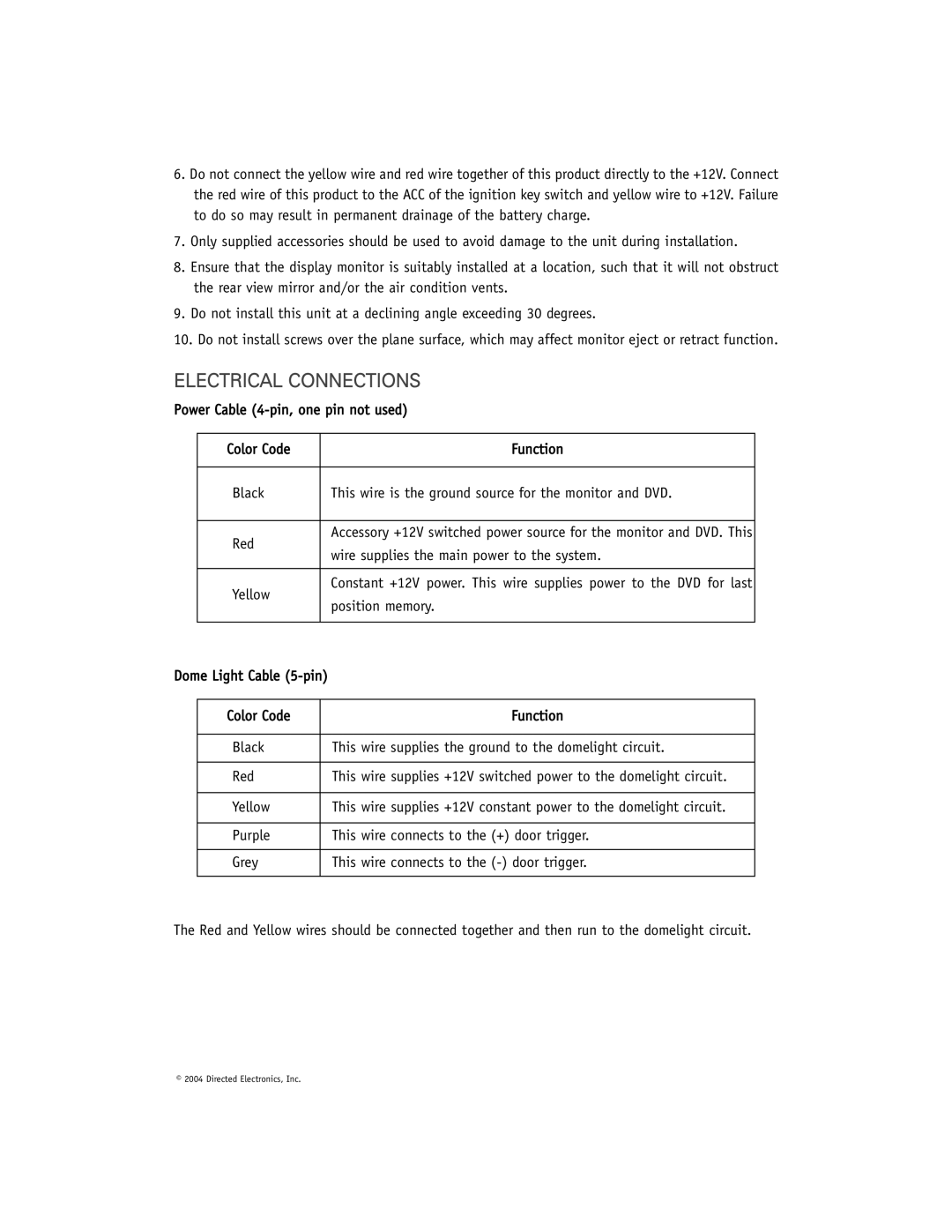
ELECTRICAL CONNECTIONS
Power Cable
| Color Code |
| Function |
|
|
|
|
| Black |
| This wire is the ground source for the monitor and DVD. |
|
|
|
|
| Red |
| Accessory +12V switched power source for the monitor and DVD. This |
|
| wire supplies the main power to the system. | |
|
|
| |
|
|
|
|
| Yellow |
| Constant +12V power. This wire supplies power to the DVD for last |
|
| position memory. | |
|
|
| |
|
|
|
|
Dome Light Cable |
| ||
|
|
|
|
| Color Code |
| Function |
|
|
|
|
| Black |
| This wire supplies the ground to the domelight circuit. |
|
|
|
|
| Red |
| This wire supplies +12V switched power to the domelight circuit. |
|
|
|
|
| Yellow |
| This wire supplies +12V constant power to the domelight circuit. |
|
|
|
|
| Purple |
| This wire connects to the (+) door trigger. |
|
|
|
|
| Grey |
| This wire connects to the |
|
|
|
|
The Red and Yellow wires should be connected together and then run to the domelight circuit.
© 2004 Directed Electronics, Inc. | 7 |
|