|
| WHS104 AUTOMOTIVE WIRELESS | |
|
| HEADPHONE SYSTEM | |
Parts Supplied | Figure | ||
z | One IR Transmitter. |
| |
z | One IR Transmitter Harness. |
| |
z | Two IR Headphones. |
| |
Important Notes |
| ||
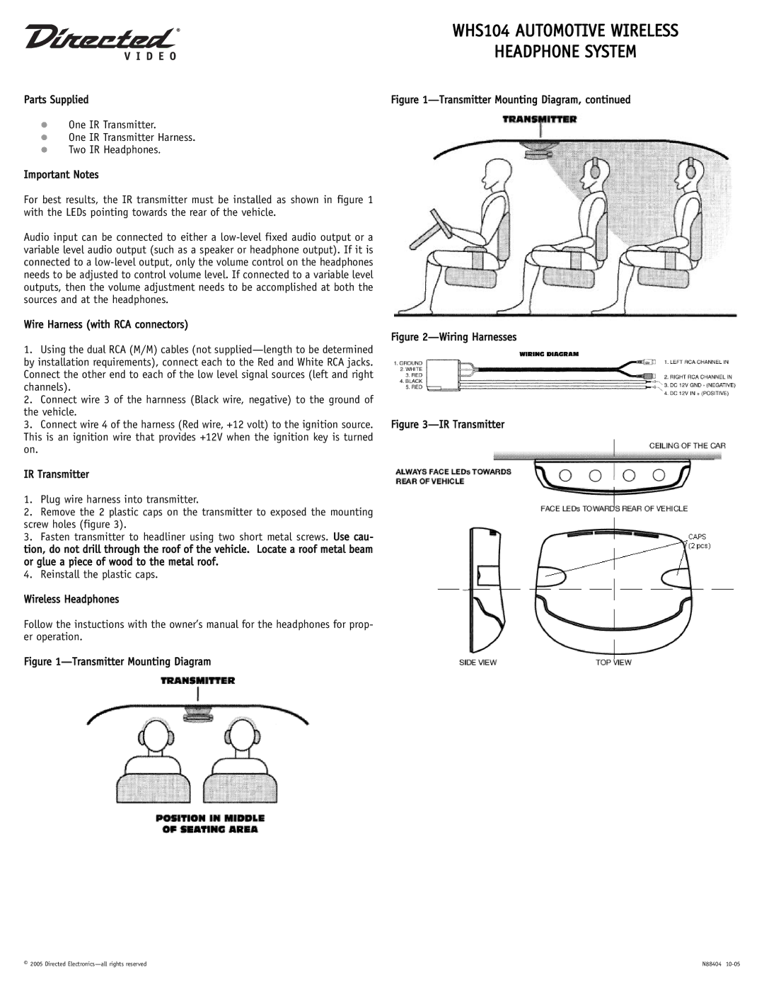
For best results, the IR transmitter must be installed as shown in figure 1 |
| ||
with the LEDs pointing towards the rear of the vehicle. |
| ||
Audio input can be connected to either a |
| ||
variable level audio output (such as a speaker or headphone output). If it is |
| ||
connected to a |
| ||
needs to be adjusted to control volume level. If connected to a variable level |
| ||
outputs, then the volume adjustment needs to be accomplished at both the |
| ||
sources and at the headphones. |
| ||
Wire Harness (with RCA connectors) | Figure | ||
1. Using the dual RCA (M/M) cables (not | |||
| |||
by installation requirements), connect each to the Red and White RCA jacks. |
| ||
Connect the other end to each of the low level signal sources (left and right |
| ||
channels). |
| ||
2. Connect wire 3 of the harnness (Black wire, negative) to the ground of |
| ||
the vehicle. | Figure | ||
3. Connect wire 4 of the harness (Red wire, +12 volt) to the ignition source. | |||
This is an ignition wire that provides +12V when the ignition key is turned |
| ||
on. |
|
| |
IR Transmitter
1.Plug wire harness into transmitter.
2.Remove the 2 plastic caps on the transmitter to exposed the mounting screw holes (figure 3).
3.Fasten transmitter to headliner using two short metal screws. Use cau- tion, do not drill through the roof of the vehicle. Locate a roof metal beam or glue a piece of wood to the metal roof.
4.Reinstall the plastic caps.
Wireless Headphones
Follow the instuctions with the owner’s manual for the headphones for prop- er operation.
Figure 1—Transmitter Mounting Diagram
© 2005 Directed | N88404 |