SERVICE AND ADJUSTMENTS

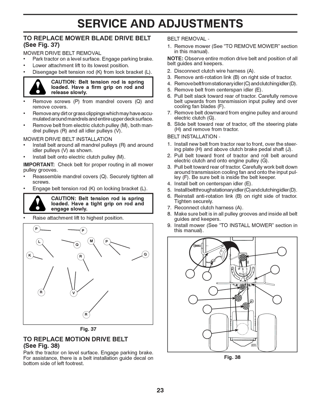
TO REPLACE MOWER BLADE DRIVE BELT (See Fig. 37)

MOWER DRIVE BELT REMOVAL

Park tractor on a level surface. Engage parking brake.

Lower attachment lift to its lowest position.

Disengage belt tension rod (K) from lock bracket (L).

CAUTION: Belt tension rod is spring loaded. Have a firm grip on rod and release slowly.

Remove screws (P) from mandrel covers (Q) and remove covers.

Removeanydirtorgrassclippingswhichmayhaveaccu- mulated around mandrels and entire upper deck surface.

Remove belt from electric clutch pulley (M), both man- drel pulleys (R) and all idler pulleys (V).

MOWER DRIVE BELT INSTALLATION

Install belt around all mandrel pulleys (R) and around idler pulleys (V) as shown.

Install belt onto electric clutch pulley (M).

IMPORTANT: Check belt for proper routing in all mower pulley grooves.

Reassemble mandrel covers (Q). Securely tighten all screws.

Engage belt tension rod (K) on locking bracket (L).

CAUTION: Belt tension rod is spring loaded. Have a tight grip on rod and engage slowly.

Raise attachment lift to highest position.

BELT REMOVAL -

1.Remove mower (See “TO REMOVE MOWER” section in this manual).

NOTE: Observe entire motion drive belt and position of all belt guides and keepers.

2.Disconnect clutch wire harness (A).

3.Remove anti-rotation link (B) on right side of tractor.

4.Removebeltfromstationaryidler(C)andclutchingidler(D).

5.Remove belt from centerspan idler (E).

6.Pull belt slack toward rear of tractor. Carefully remove belt upwards from transmission input pulley and over cooling fan blades (F).

7.Remove belt downward from engine pulley and around electric clutch (G).

8.Slide belt toward rear of tractor, off the steering plate

(H) and remove from tractor.

BELT INSTALLATION -

1.Install new belt from tractor rear to front, over the steer- ing plate (H) and above clutch brake pedal shaft (J).

2.Pull belt toward front of tractor and roll belt around electric clutch and onto engine pulley (G).

3.Pull belt toward rear of tractor. Carefully work belt down around transmission cooling fan and onto the input pul- ley (F). Be sure belt is inside the belt keeper.

4.Install belt on centerspan idler (E).

5.Installbeltthroughstationaryidler(C)andclutchingidler(D).

6.Reinstall anti-rotation link (B) on right side of tractor. Tighten securely.

7.Reconnect clutch harness (A).

8.Make sure belt is in all pulley grooves and inside all belt guides and keepers.

9.Install mower (See “TO INSTALL MOWER” section in

P

P


L

M

P


Q


K

R

Q

this manual).

B A

G

H

R

V


R

Fig. 37

TO REPLACE MOTION DRIVE BELT (See Fig. 38)

Park the tractor on level surface. Engage parking brake. For assistance, there is a belt installation guide decal on bottom side of left footrest.


C

D

J


E

F

02953 electric

Fig. 38

23

Page 23
Image 23
Dixon D26BH54, 434722 manual To Replace Mower Blade Drive Belt See Fig, To Replace Motion Drive Belt See Fig

D26BH54, 434722 specifications

The Dixon D26BH54,434722 is an advanced piece of technology that stands out in the realm of its application. This versatile product has been designed to offer both functionality and efficiency, catering to a diverse range of industries and users. Key features of the Dixon D26BH54 include its robust construction and ergonomic design, ensuring durability and ease of use in various work environments.

One primary characteristic of the D26BH54 is its innovative blend of materials, which allows it to withstand harsh conditions while maintaining a lightweight profile. This is particularly crucial for users who rely on mobility and adaptability in their tasks. The product is also engineered with cutting-edge technology that enhances performance and optimizes energy consumption, making it not only effective but also environmentally friendly.

In terms of functionality, the Dixon D26BH54 is equipped with a range of advanced features that simplify operations. Users can benefit from an intuitive interface that allows for easy navigation and quick adjustments, ultimately improving workflow efficiency. This model integrates smart technology, enabling it to collect and analyze data in real-time, which in turn aids in decision-making processes and operational enhancements.

Furthermore, the D26BH54’s compatibility with various accessories and attachments broadens its utility. This modularity ensures that users can tailor the product to meet their specific needs, adding to its overall versatility. The ability to incorporate additional features as required makes it particularly appealing for businesses looking to adapt to changing demands.

Safety is another critical consideration in the design of the Dixon D26BH54. It incorporates various safety mechanisms and features, ensuring user protection and minimizing potential risks during operation. The inclusion of ergonomic components also promotes user comfort, reducing the likelihood of injury and allowing for extended use without fatigue.

In summary, the Dixon D26BH54,434722 is not just a product but a comprehensive solution designed to enhance efficiency and performance across various applications. With its robust features, integration of smart technology, and focus on safety and user comfort, it is poised to meet the evolving needs of its users, making it a valuable asset in any professional toolkit.