SERVICE AND ADJUSTMENTS

WARNING: TO AVOID SERIOUS INJURY, BEFORE PERFORMING ANY SERVICE OR ADJUSTMENTS:

Depress brake pedal fully and set parking brake.

Place attachment clutch in “DISENGAGED” position.

Turn ignition key to “STOP” and remove key.

Make sure the blades and all moving parts have completely stopped.

Disconnect spark plug wire from spark plug and place wire where it cannot come in contact with plug.

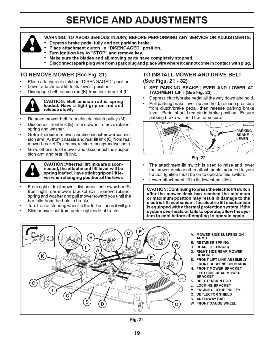
TO REMOVE MOWER (See Fig. 21)

Place attachment clutch in “DISENGAGED” position.

Lower attachment lift to its lowest position.

Disengage belt tension rod (K) from lock bracket (L).

CAUTION: Belt tension rod is spring loaded. Have a tight grip on rod and release slowly.

Remove mower belt from electric clutch pulley (M).

Disconnect front link (E) from mower - remove retainer spring and washer.

Gotoeithersideofmoweranddisconnectmowersuspen- sion arm (A) from chassis and rear lift link (C) from rear mowerbracket(D)-removeretainerspringsandwashers.

Go to other side of mower and disconnect the suspen- sion arm and rear lift link.

TO INSTALL MOWER AND DRIVE BELT (See Figs. 21 - 32)

1.SET PARKING BRAKE LEVER AND LOWER AT- TACHMENT LIFT (See Fig. 22)

Depress clutch/brake pedal all the way down and hold.

Pull parking brake lever up and hold, release pressure from clutch/brake pedal, then release parking brake lever. Pedal should remain in brake position. Ensure parking brake will hold tractor secure.

PARKING

BRAKE

LEVER

Fig. 22

CAUTION: After rear lift links are discon- nected, the attachment lift lever will be spring loaded. Have a tight grip on lift le- ver when changing position of the lever.

From right side of mower, disconnect anti-sway bar (S) from right rear mower bracket (D) - remove retainer spring and washer and pull mower toward you until the bar falls from the hole in bracket.

Turn tractor steering wheel to the left as far as it will go.

Slide mower out from under right side of tractor.

The attachment lift switch is used to raise and lower the mower deck or other attachments mounted to your tractor. Ignition must be on to operate this switch.

Lower attachment lift to its lowest position.

CAUTION: Continuing to press the electric lift switch after the mower deck has reached the minimum or maximum position may result in damage to the electric lift mechanism.The electric lift mechanism is equipped with a thermal protection system. If the system overheats or fails to operate, allow the sys- tem to cool before attempting to operate again.

B

L A K

C

I

C

S D

M

F


A. MOWER SIDE SUSPENSION


ARMS


W


B. RETAINER SPRING


C. REAR LIFT LINK(S)


D. RIGHT SIDE REAR MOWER


E


BRACKET


E. FRONT LIFT LINK ASSEMBLY


F. FRONT SUSPENSION BRACKET


H. FRONT MOWER BRACKET


I.

LEFT SIDE REAR MOWER


H


BRACKET


K. BELT TENSION ROD


L. LOCKING BRACKET


M. ENGINE CLUTCH PULLEY


Q. DEFLECTOR SHIELD


S. ANTI-SWAY BAR


Q


W. FRONT GAUGE WHEEL

Fig. 21

19

Page 19
Image 19
Dixon D26BH54, 434722 manual Service and Adjustments, To Remove Mower See Fig, To Install Mower and Drive Belt See Figs

D26BH54, 434722 specifications

The Dixon D26BH54,434722 is an advanced piece of technology that stands out in the realm of its application. This versatile product has been designed to offer both functionality and efficiency, catering to a diverse range of industries and users. Key features of the Dixon D26BH54 include its robust construction and ergonomic design, ensuring durability and ease of use in various work environments.

One primary characteristic of the D26BH54 is its innovative blend of materials, which allows it to withstand harsh conditions while maintaining a lightweight profile. This is particularly crucial for users who rely on mobility and adaptability in their tasks. The product is also engineered with cutting-edge technology that enhances performance and optimizes energy consumption, making it not only effective but also environmentally friendly.

In terms of functionality, the Dixon D26BH54 is equipped with a range of advanced features that simplify operations. Users can benefit from an intuitive interface that allows for easy navigation and quick adjustments, ultimately improving workflow efficiency. This model integrates smart technology, enabling it to collect and analyze data in real-time, which in turn aids in decision-making processes and operational enhancements.

Furthermore, the D26BH54’s compatibility with various accessories and attachments broadens its utility. This modularity ensures that users can tailor the product to meet their specific needs, adding to its overall versatility. The ability to incorporate additional features as required makes it particularly appealing for businesses looking to adapt to changing demands.

Safety is another critical consideration in the design of the Dixon D26BH54. It incorporates various safety mechanisms and features, ensuring user protection and minimizing potential risks during operation. The inclusion of ergonomic components also promotes user comfort, reducing the likelihood of injury and allowing for extended use without fatigue.

In summary, the Dixon D26BH54,434722 is not just a product but a comprehensive solution designed to enhance efficiency and performance across various applications. With its robust features, integration of smart technology, and focus on safety and user comfort, it is poised to meet the evolving needs of its users, making it a valuable asset in any professional toolkit.