CONTROLS
This operator’s manual describes the Dixon Zero Turn Rider. The rider is fitted with a Kohler 25 HP* four- stroke overhead valve engine.
Transmission from the engine is made via
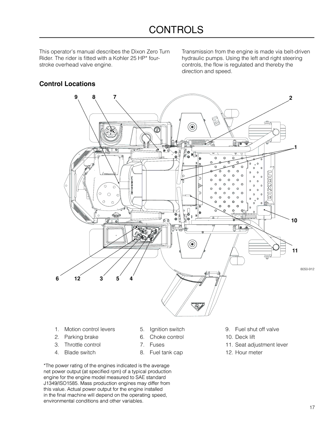
Control Locations
9 | 8 | 7 | 2 |
1
10
11
6 | 12 | 3 | 5 | 4 |
1. | Motion control levers | 5. | Ignition switch | 9. | Fuel shut off valve |
2. | Parking brake | 6. | Choke control | 10. | Deck lift |
3. | Throttle control | 7. | Fuses | 11. | Seat adjustment lever |
4. | Blade switch | 8. | Fuel tank cap | 12. | Hour meter |
*The power rating of the engines indicated is the average net power output (at specified rpm) of a typical production engine for the engine model measured to SAE standard J1349/ISO1585. Mass production engines may differ from this value. Actual power output for the engine installed
in the final machine will depend on the operating speed, environmental conditions and other variables.
17