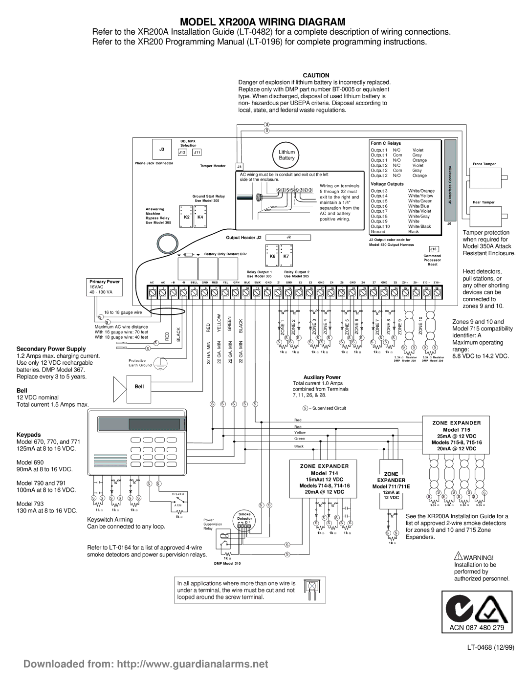
MODEL XR200A WIRING DIAGRAM
Refer to the XR200A Installation Guide
CAUTION
Danger of explosion if lithium battery is incorrectly replaced. Replace only with DMP part number
|
|
|
|
|
|
|
|
|
|
|
| s |
|
|
|
|
|
|
|
|
|
|
|
|
|
|
|
|
|
|
|
|
| s |
|
|
|
|
|
|
|
|
|
|
|
|
| DD, MPX |
|
|
|
|
|
|
|
|
|
|
|
|
|
|
|
| |
|
| J3 |
| Selection |
|
|
|
|
|
|
|
|
|
|
|
|
|
|
|
| |
|
|
| J12 | J11 |
|
|
|
|
|
| Lithium |
|
|
|
|
|
|
| |||
|
|
|
|
|
|
|
|
|
|
|
|
|
|
|
|
| |||||
|
|
|
|
|
|
|
|
|
|
|
|
| Battery |
|
|
|
|
|
|
| |
| Phone Jack Connector |
|
| Tamper Header | J4 |
|
|
|
|
|
|
|
|
|
|
| |||||
|
|
|
|
|
|
|
|
|
|
|
|
|
|
|
|
| |||||
|
|
|
|
|
|
|
|
|
| AC wiring must be in conduit and exit out the left |
|
|
|
| |||||||
|
|
|
|
|
|
|
|
|
| side of the enclosure. |
|
|
|
|
|
|
|
| |||
|
|
|
|
|
|
|
|
|
|
|
|
|
|
|
|
| Wiring on terminals |
| |||
|
|
|
|
|
|
|
|
|
|
|
|
|
|
|
|
| 5 through 22 must |
| |||
|
|
|
|
| Ground Start Relay |
|
|
|
|
|
|
|
| exit to the right and |
| ||||||
|
|
|
|
| Use Model 305 |
|
|
|
|
|
|
|
|
| maintain a 1/4" |
| |||||
|
|
|
|
|
|
|
|
|
|
|
|
|
|
|
|
|
| ||||
| Answering |
|
|
|
|
|
|
|
|
|
|
|
|
|
| separation from the |
| ||||
| Machine |
| K2 | K4 |
|
|
|
|
|
|
|
|
|
| AC and battery |
| |||||
| Bypass Relay |
|
|
|
|
|
|
|
|
|
|
| positive wiring. |
| |||||||
| Use Model 305 |
|
|
|
|
|
|
|
|
|
|
|
|
|
|
| |||||
|
|
|
|
|
|
|
|
|
|
|
|
|
|
|
|
|
|
|
| ||
|
|
|
|
|
|
|
| Output Header J2 |
|
| J2 |
|
|
|
|
|
|
| |||
|
|
|
|
|
| Battery Only Restart CR7 |
| K6 |
| K7 |
|
|
|
|
|
|
| ||||
|
|
|
|
|
|
|
|
|
|
|
|
|
|
|
|
|
|
|
| ||
|
|
|
|
|
|
|
|
|
| Relay Output 1 |
| Relay Output 2 |
|
|
|
|
| ||||
|
|
|
|
|
|
|
|
|
| Use Model 305 |
| Use Model 305 |
|
|
|
|
|
| |||
Primary Power | AC | AC | +B | BELL | GND | RED | YEL | GRN | BLK | SMK | GND | Z1 | GND | Z2 | Z3 | GND | Z4 | Z5 | GND | Z6 | |
16VAC | 1 | 2 | 3 | 4 | 5 | 6 | 7 | 8 | 9 | 10 | 11 | 12 | 13 | 14 | 15 | 16 | 17 | 18 | 1 | 20 | 21 |
40 - 100 VA |
|
|
|
|
|
|
|
|
|
|
|
|
|
|
|
|
|
| 9 |
|
|
|
|
|
|
|
|
|
|
|
|
|
|
|
|
|
|
|
|
|
|
| |
16 to 18 gauge wire |
|
|
|
|
|
|
|
|
|
|
|
|
|
|
|
|
|
|
|
| |
Form C Relays |
|
|
|
|
|
|
|
|
|
| |||
Output 1 | N/C |
|
| Violet |
|
|
|
| |||||
Output 1 | Com |
|
| Gray |
|
|
|
|
|
|
| ||
Output 1 | N/O |
|
| Orange |
|
|
|
| |||||
Output 2 | N/C |
|
| Violet |
|
|
| Connector | |||||
Output 2 | Com |
|
| Gray |
|
|
|
|
|
| |||
Output 2 | N/O |
|
| Orange |
|
|
|
| |||||
Voltage Outputs | White/Yellow |
|
|
| Interface | ||||||||
Output 4 |
|
|
|
|
|
| |||||||
Output 3 |
|
|
| White/Orange |
|
| |||||||
Output 5 |
|
|
| White/Green |
|
|
| J6 | |||||
Output 6 |
|
|
| White/Blue |
|
|
|
| |||||
Output 7 |
|
|
| White/Violet |
|
|
|
| |||||
Output 8 |
|
|
| White/Gray |
|
|
|
| |||||
Output 9 |
|
|
| White |
|
|
|
|
|
| J6 | ||
Output 10 |
|
|
| White/Black |
|
|
| ||||||
|
|
|
|
|
|
| |||||||
Ground |
|
|
| Black |
|
|
|
|
|
|
| ||
J2 Output color code for |
|
|
|
|
|
|
| ||||||
Model 430 Output Harness |
|
|
|
|
|
|
| ||||||
|
|
|
|
|
|
|
| J16 |
|
|
| ||
|
|
|
|
|
|
| Command |
|
| ||||
|
|
|
|
|
|
| Processor |
|
| ||||
|
|
|
|
|
|
| Reset |
|
| ||||
Z7 | GND | Z8 | Z9 + |
| Z9 - | Z10 + | Z10 - |
|
| ||||
22 | 23 | 24 |
| 25 |
| 26 | 27 |
|
| 28 |
|
|
|
|
|
|
|
|
|
|
|
|
|
|
|
|
|
Front Tamper
Rear Tamper
Tamper protection when required for Model 350A Attack Resistant Enclosure.
Heat detectors, pull stations, or any other shorting devices can be connected to zones 9 and 10.
s | s |
|
|
| MIN YELLOW | GREEN | MIN BLACK |
| ZONE 2 |
|
| ZONE 5 |
|
|
|
| RED |
|
|
|
| ||||||
Maximum AC wire distance |
| BLACK |
|
|
|
| |||||||
With 16 gauge wire: 70 feet | RED | s | s | s | s | ||||||||
With 18 guage wire: 40 feet |
|
| s | s | |||||||||
| s | MIN | MIN | s | s | s | s | s | s | ||||
Secondary Power Supply | s | ZONE1 |
| ZONE3 | ZONE4 |
| ZONE6 | ||||||
|
| GA. | GA. | GA. | GA. | 1k Ω | 1k Ω | 1k Ω | 1k Ω | 1k Ω | 1k Ω | ||
1.2 Amps max. charging current. |
|
|
| ||||||||||
|
|
|
|
|
|
|
|
| |||||
Use only 12 VDC rechargable | Protective |
|
| 22 | 22 | 22 | 22 |
|
|
|
|
|
|
Earth Ground |
|
|
|
|
|
|
|
| |||||
|
|
|
|
|
|
|
|
|
|
|
| ||
batteries. DMP Model 367. |
|
|
|
|
|
|
|
|
|
|
|
|
|
Replace every 3 to 5 years. |
|
|
|
|
|
|
|
|
| Auxiliary Power |
| ||
| Bell |
|
|
|
|
|
|
| Total current 1.0 Amps |
| |||
Bell |
|
|
|
|
|
|
| combined from Terminals |
| ||||
|
|
|
|
|
|
|
|
| |||||
12 VDC nominal |
|
|
|
|
|
|
|
| 7, 11, 26, & 28. |
|
| ||
|
|
|
| s s | s | s | s |
|
|
|
|
| |
Total current 1.5 Amps max. |
|
|
|
|
| s = Supervised Circuit |
| ||||||
|
|
|
|
|
|
|
|
|
|
| |||
|
|
|
|
|
|
|
|
| Red |
|
|
|
|
|
|
|
|
|
|
|
|
| Red |
|
|
|
|
Keypads |
|
|
|
|
|
|
|
| Yellow |
|
|
| |
|
|
|
|
|
|
|
| Green |
|
|
| ||
Model 670, 770, and 771 |
|
|
|
|
|
|
|
|
|
|
| ||
|
|
|
|
|
|
|
| Black |
|
|
| ||
125mA at 8 to 16 VDC. |
|
|
|
|
|
|
|
|
|
|
| ||
|
|
|
|
|
|
|
|
|
|
|
|
| |
Model 690 |
|
|
|
|
|
|
|
| ZONE EXPANDER |
| |||
90mA at 8 to 16 VDC. |
|
|
|
|
|
|
|
|
| ||||
|
|
|
|
|
|
|
|
| Model 714 |
|
| ||
|
|
|
|
|
|
|
|
|
|
|
| ||
Model 790 and 791 | s s |
|
|
|
|
|
|
|
| 15mAat 12 VDC |
| ||
|
|
|
|
|
|
| Models |
| |||||
100mA at 8 to 16 VDC. |
|
|
|
|
|
|
|
|
| ||||
|
| D I S A R M |
|
|
|
|
|
| 20mA @ 12 VDC |
| |||
7 | 8 | 9 |
| 10 |
| Zones 9 and 10 and |
ZONE | ZONE | ZONE |
| ZONE |
| |
|
| Model 715 compatibility | ||||
|
|
|
|
|
| |
s |
| s |
|
|
| identifier: A |
s | s | s | s |
| s s | Maximum operating |
|
|
| range: | |||
1k Ω | 1k Ω |
|
|
| ||
|
| 3 . 3k Ω Resistor 8.8 VDC to 14.2 VDC. | ||||
|
| 3 . 3k Ω | Resistor |
| ||
|
| DMP Model 309 | DMP Model 309 |
| ||
ZONE EXPANDER
Model 715
25mA @ 12 VDC
Models
20mA @ 12 VDC
ZONE
EXPANDER
Model 711/711E
12mA at | s | s | s | s |
Model 793
130 mA at 8 to 16 VDC.
s s | s s | s s |
|
|
| |
|
|
| A R M |
| s s | |
1k Ω | 1k Ω | 1k Ω |
|
|
| |
|
|
| 1k Ω |
| Smoke | |
Keyswitch Arming | Power | Detector | ||||
| ||||||
Can be connected to any loop. |
| Supervision | Ð + | |||
| Relay |
| ||||
Refer to | s |
| |
smoke detectors and power supervision relays. | s |
| 1k Ω |
| DMP Model 310 |
ss ![]()
![]()
![]()
s s s s
1k Ω 1k Ω | 1k Ω |
12 VDC | s | s | s | s |
|
| 3 . 3k Ω 3 . 3k Ω | 3 . 3k Ω | 3 . 3k Ω |
See the XR200A Installation Guide for a list of approved
s s for zones 9 and 10 and 715 Zone Expanders.
1k Ω
! WARNING! Installation to be performed by authorized personnel.
In all applications where more than one wire is under a terminal, the wire must be cut and not looped around the screw terminal.
ACN 087 480 279
Downloaded from: http://www.guardianalarms.net