220 V Revelation by DRAPERPage 6 of 8
Field Installation of Plenum Kit
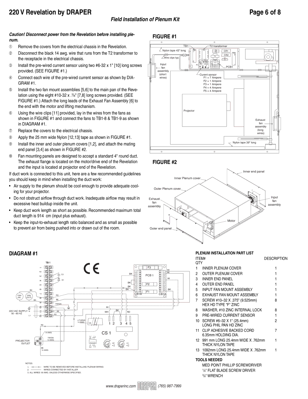
Caution! Disconnect power from the Revelation before installing ple- | FIGURE #1 | |
num. | ||
|
➀Remove the covers from the electrical chassis in the Revelation.
➁Disconnect the black 14 awg. wire that runs from the T2 transformer to the receptacle in the electrical chassis.
➂Install the
➃Connect each wire of the
➄Install the two fan mount assemblies [5,6] to the main pan of the Reve- lation using the eight
➅Using the wire clips [11] provided, lay in the wires from the fans as shown in FIGURE #1 and connect the fans to
➆Replace the covers to the electrical chassis.
➇Apply the 25 mm wide Nylon [12,13] tape as shown in FIGURE #1.
➈Install the inner and outer plenum covers [1,2], and attach the mating end panel [3,4] as shown in FIGURE #2.
TB1 |
|
Nylon tape 43" long | 1 |
| TB1 |
Wire clips typ. |
|
| 12 |
InputBK ![]() fan
fan
assembly (short wires)
Projector
![]() T2 transformer
T2 transformer
T2 |
|
|
| F4 |
| CR1 |
|
|
|
|
| F5 |
|
| TB2 |
|
|
|
| T1 |
| CR2 | 12 |
|
|
|
|
|
| ||
|
|
|
|
|
|
| |
BK WH BK | RD |
| F3 |
| C1 |
| |
|
|
| 1 |
| 1 |
|
|
CS1 | 3 4 5 | CB1B | PCB1 | CB1A |
| 1 | |
F2 |
| ||||||
1 2 |
|
|
|
|
| ||
10 | F1 | 10 | PCB1 |
|
|
|
Curent sensor
F1 = 7 Ampere
F2 = 1 Ampere
F3 = 1 Ampere
F4 = 4 Ampere
F5 = 4 Ampere
Exhaust fan assembly (long wires)
Nylon tape 39" long
➉Fan mounting panels are designed to accept a standard 4" round duct. The exhaust fl ange is located on the motor/drive end of the Revelation and the input is located at projector end of the Revelation.
If duct work is connected to this unit, here are a few recommended guidelines you should keep in mind when installing the duct work:
•Air supply to the plenum should be cool enough to provide adequate cool- ing for your projector.
FIGURE #2
Inner end panel
Inner Plenum cover
Outer Plenum cover
• Do not obstruct airfl ow through duct work. Inadequate airflow may result in | Exhaust | |
excessive heat buildup inside the unit. | fan | |
assembly | ||
|
Input ![]() fan
fan
assembly
•Keep duct work length as short as possible. Recommended maximum total duct length is 914 cm (input plus exhaust).
•Keep the
to prevent air from being pushed into or drawn out of the room. | Outer end panel |
Motor
DIAGRAM #1
|
| TB 1 |
|
|
| 1 |
|
|
| 2 |
|
|
| 3 | C2 |
|
|
| |
|
| 4 | D1 |
|
| 5 |
|
| BK | 6 |
|
|
|
| |
FAN | FAN | 7 | RD |
| |||
(IN) | (OUT) | 8 | BE |
| BK |
| |
|
| 9 | YW/GN |
|
|
| |
|
| 10 |
|
220 VAC SUPPLY N | 11 | BE | |
50 - 60 HZ | 12 | RD | |
| L1 | ||
|
| ||
|
| RD |
|
|
| 14 AWG |
|
|
| YW/GN |
|
PROJECTOR | 14 AWG |
| |
| OUTLET |
|
|
|
| BE |
|
|
| 14 AWG |
|
|
|
|
|
|
|
| F3 |
|
|
|
|
|
| BK | 1 |
| 1 |
|
|
|
|
| 2 | PCB 1 | 2 | |
|
|
|
|
|
| 3 | 3 | |
|
|
|
|
|
| 4 |
| 4 |
|
|
|
|
|
| 5 |
| 5 |
|
|
|
|
| BK | 6 | F2 | 6 |
|
|
|
|
| 7 | 7 | ||
|
|
|
|
| BK | |||
|
|
|
|
| 8 |
| 8 | |
|
|
|
| BK | 9 |
| 9 | |
|
|
|
| 10 | F1 | 10 | ||
|
|
|
|
|
| |||
|
|
|
|
|
| CB1B | CB1A | |
|
|
|
|
|
|
| ||
| BE |
|
|
|
|
|
|
|
| WH |
| BK | RD |
|
|
| |
|
|
|
|
|
| |||
4 TURNS |
|
|
|
|
|
|
|
|
14 AWG | 1 | 2 | 3 | 4 | 5 |
|
|
|
|
|
|
| |||||
| CS 1 |
|
|
|
|
|
|
|
| I |
|
|
|
|
|
|
|
|
| t |
| I |
|
|
| |
| I |
|
|
|
|
|
|
|
BE
BE
BE
BK
PLENUM INSTALLATION PART LIST |
|
| |
ITEM# | DESCRIPTION | ||
QTY |
|
| |
1 | INNER PLENUM COVER |
| 1 |
2 | OUTER PLENUM COVER |
| 1 |
3 | INNER END PANEL |
| 1 |
4 | OUTER END PANEL |
| 1 |
5 | INPUT FAN MOUNT ASSEMBLY |
| 1 |
6 | EXHAUST FAN MOUNT ASSEMBLY |
| 1 |
7 | SCREW |
| 8 |
| HEX HD TYPE "F" ZINC |
|
|
8 | WASHER, #10 ZINC INTERNAL LOCK |
| 8 |
9 |
| 1 | |
10 | SCREW |
| 2 |
| LONG PHIL PAN HD ZINC |
|
|
11 | CLIP ADHESIVE BACKED CORD |
| 7 |
| 6.35mm HOLDING DIA. |
|
|
12 | 991 mm LONG 25.4mm WIDE X .762mm | 1 | |
| THICK NYLON TAPE |
|
|
13 | 1092mm LONG 25.4mm WIDE X .762mm | 1 | |
| THICK NYLON TAPE |
|
|
TOOLS NEEDED
NOTES:
1. ![]() WIRE TO BE REMOVED BEFORE INSTALLING PLENUM WIRING
WIRE TO BE REMOVED BEFORE INSTALLING PLENUM WIRING
2.WIRES CONNECTED BY INSTALLER
3.ALL WIRES 18 AWG. UNLESS OTHERWISE SPECIFIED.
MED POINT PHILLIP SCREWDRIVER 1/8" FLAT BLADE SCREW DRIVER 3/8" WRENCH
www.draperinc.com ![]()
![]()
![]()
![]()
![]() (765)
(765)