220 V Revelation by DRAPER
VIC12 Kit Installation Instructions
Page 8 of 8
The VIC 12 KIT includes all the components necessary for the VIC 12 to work with the Revelation. Follow these steps to install the components in this KIT.
➀Close the door to the Revelation.
➁DISCONNECT POWER TO THE REVELATION.
➂Remove the covers from the electrical enclosure.
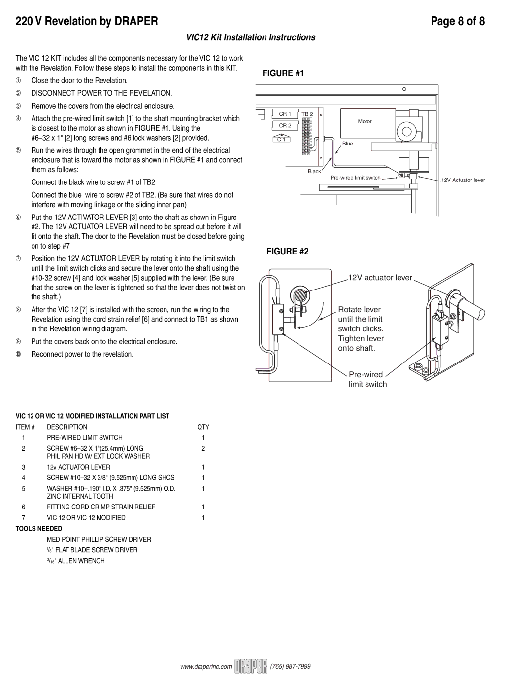
➃Attach the
➄Run the wires through the open grommet in the end of the electrical enclosure that is toward the motor as shown in FIGURE #1 and connect them as follows:
Connect the black wire to screw #1 of TB2
Connect the blue wire to screw #2 of TB2. (Be sure that wires do not interfere with moving linkage or the sliding inner pan)
➅Put the 12V ACTIVATOR LEVER [3] onto the shaft as shown in Figure #2. The 12V ACTUATOR LEVER will need to be spread out before it will fi t onto the shaft. The door to the Revelation must be closed before going on to step #7
➆Position the 12V ACTUATOR LEVER by rotating it into the limit switch until the limit switch clicks and secure the lever onto the shaft using the
FIGURE #1
CR 1 | TB 2 |
| |
CR 2 | 9 10 | Motor | |
| |||
C 1 | 5 6 7 8 | Blue | |
3 4 | |||
| |||
| 1 2 |
|
Black
![]()
FIGURE #2
12V actuator lever
12V Actuator lever
➇After the VIC 12 [7] is installed with the screen, run the wiring to the Revelation using the cord strain relief [6] and connect to TB1 as shown in the Revelation wiring diagram.
➈Put the covers back on to the electrical enclosure.
➉Reconnect power to the revelation.
Rotate lever ![]() until the limit switch clicks. Tighten lever
until the limit switch clicks. Tighten lever
onto shaft.
VIC 12 OR VIC 12 MODIFIED INSTALLATION PART LIST
ITEM # | DESCRIPTION | QTY |
1 | 1 | |
2 | SCREW | 2 |
| PHIL PAN HD W/ EXT LOCK WASHER |
|
3 | 12v ACTUATOR LEVER | 1 |
4 | SCREW | 1 |
5 | WASHER | 1 |
| ZINC INTERNAL TOOTH |
|
6 | FITTING CORD CRIMP STRAIN RELIEF | 1 |
7 | VIC 12 OR VIC 12 MODIFIED | 1 |
TOOLS NEEDED
MED POINT PHILLIP SCREW DRIVER I/8" FLAT BLADE SCREW DRIVER 3/16" ALLEN WRENCH
www.draperinc.com ![]()
![]()
![]()
![]()
![]()
![]() (765)
(765)
