Ducane (HVAC) 2HP13 Opening Service Valves, Install Electrical Accessories, Control Wiring

Models: 2HP13

1 18
Download 18 pages 21.7 Kb
Page 5
Image 5

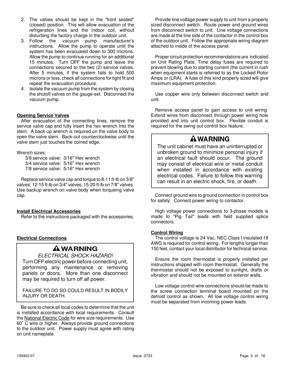
2.The valves should be kept in the "front seated" (closed) position. This will allow evacuation of the refrigeration lines and the indoor coil, without disturbing the factory charge in the outdoor unit.

3.Follow the vacuum pump manufacturer's instructions. Allow the pump to operate until the system has been evacuated down to 300 microns. Allow the pump to continue running for an additional 15 minutes. Turn OFF the pump and leave the connections secured to the two (2) service valves. After 5 minutes, if the system fails to hold 500 microns or less, check all connections for tight fit and repeat the evacuation procedure.

4.Isolate the vacuum pump from the system by closing the shutoff valves on the gauge-set. Disconnect the vacuum pump.

Opening Service Valves

After evacuation of the connecting lines, remove the service valve cap and fully insert the hex wrench into the stem. A back-up wrench is required on the valve body to open the valve stem. Back-out counterclockwise until the valve stem just touches the coined edge.

Wrench sizes:

3/8 service valve: 3/16" Hex wrench

3/4 service valve: 5/16" Hex wrench

7/8 service valve: 5/16" Hex wrench

Replace service valve cap and torque to 8-11 ft-lb on 3/8" valves; 12-15 ft-lb on 3/4" valves; 15-20 ft-lb on 7/8" valves. Use backup wrench on valve body when torqueing valve cap.

Install Electrical Accessories

Refer to the instructions packaged with the accessories.

Electrical Connections

. . . .

ELECTRICAL SHOCK HAZARD!

Turn OFF electric power before connecting unit, performing any maintenance or removing panels or doors. More than one disconnect may be required to turn off all power.

FAILURE TO DO SO COULD RESULT IN BODILY INJURY OR DEATH.

Be sure to check all local codes to determine that the unit is installed accordance with local requirements. Consult the National Electric Code for wire size requirements. Use 60/ C wire or higher. Always provide ground connections to the outdoor unit. Power supply must agree with rating on unit nameplate.

Provide line voltage power supply to unit from a properly sized disconnect switch. Route power and ground wires from disconnect switch to unit. Line voltage connections are made at the line side of the contactor in the control box of the outdoor unit. Follow the appropriate wiring diagram attached to inside of the access panel.

Proper circuit protection recommendations are indicated on Unit Rating Plate. Time delay fuses are required to prevent blowing due to starting current (the current in rush when equipment starts is referred to as the Locked Rotor Amps or (LRA). A fuse of this kind properly sized will give maximum equipment protection.

Use copper wire only between disconnect switch and unit.

Remove access panel to gain access to unit wiring. Extend wires from disconnect through power wiring hole provided and into unit control box. Flexible conduit is required for the swing out control box feature.

The unit cabinet must have an uninterrupted or unbroken ground to minimize personal injury if an electrical fault should occur. The ground may consist of electrical wire or metal conduit when installed in accordance with existing electrical codes. Failure to follow this warning can result in an electric shock, fire, or death.

Connect ground wire to ground connection in control box for safety. Connect power wiring to contactor.

High voltage power connections to 3-phase models is made to "Pig Tail" leads with field supplied splice connectors.

Control Wiring

The control voltage is 24 Vac. NEC Class I insulated 18 AWG is required for control wiring. For lengths longer than 150 feet, contact your local distributor for technical service.

Ensure the room thermostat is properly installed per instructions shipped with room thermostat. Generally the thermostat should not be exposed to sunlight, drafts or vibration and should not be mounted on exterior walls.

Low voltage control wire connections should be made to the screw connection terminal board mounted on the defrost control as shown. All low voltage control wiring must be separated from incoming power leads.

100402-07

Issue 0733

Page 5 of 18

Page 5
Image 5
Ducane (HVAC) 2HP13 warranty Opening Service Valves, Install Electrical Accessories, Electrical Connections, Control Wiring

2HP13 specifications

Ducane, a well-respected name in the HVAC industry, offers a range of innovative heating, ventilation, and air conditioning solutions. One standout model in their lineup is the Ducane 2HP13, a 13 SEER central air conditioning unit that combines efficiency, reliability, and advanced technology to create comfortable indoor climates.

One of the main features of the Ducane 2HP13 is its efficient 13 SEER rating, which stands for Seasonal Energy Efficiency Ratio. This rating indicates that the unit consumes less energy compared to standard models, resulting in lower utility bills and a reduced environmental footprint. The 2HP13 is built for both cooling and heating applications, making it a versatile addition to any home or commercial space.

The Ducane 2HP13 utilizes a durable, all-aluminum coil that offers superior heat transfer capabilities and corrosion resistance. This enhances the unit's efficiency and longevity, ensuring that it continues to perform optimally over the years. The cabinet is constructed from heavy-duty steel with a baked-on powder coat finish, which provides an extra layer of protection against the elements and ensures that the unit maintains its aesthetic appeal.

In terms of indoor comfort, the Ducane 2HP13 employs a high-efficiency scroll compressor. This technology reduces noise levels and improves overall performance, ensuring that your indoor environment remains quiet and comfortable. Additionally, the compressor is equipped with built-in protective features that help safeguard it from potential operational issues, extending its lifespan.

The 2HP13 model also includes a reliable multi-speed blower motor that enhances airflow within the system. This allows for adjustable performance levels which can be tailored to the specific needs of the space, contributing to improved energy efficiency. The unit also supports diagnostic capabilities, allowing for easy maintenance and repair, minimizing downtime in case of any issues.

Furthermore, the Ducane 2HP13 is designed with a user-friendly interface that makes it easy for homeowners to operate. It also integrates seamlessly with various smart thermostats to enhance system control and contribute to even greater energy savings.

In summary, the Ducane 2HP13 embodies a perfect balance of efficiency, reliability, and user-friendly features. Its durable construction, advanced compressor technology, and high-performance capabilities make it an excellent choice for anyone looking to enhance their indoor climate while minimizing their energy consumption. With its strong reputation in the HVAC industry, Ducane ensures that the 2HP13 meets the needs of modern homeowners and businesses alike.