Operation
Controls |
|
Level switch. | This sets the input sensitivity of the unit. The +4 position is intended for |
| professional use and means that full power is reached with an input level of |
| +4dBm (balanced). The |
| domestic use and means that full power is reached with an input level of |
| |
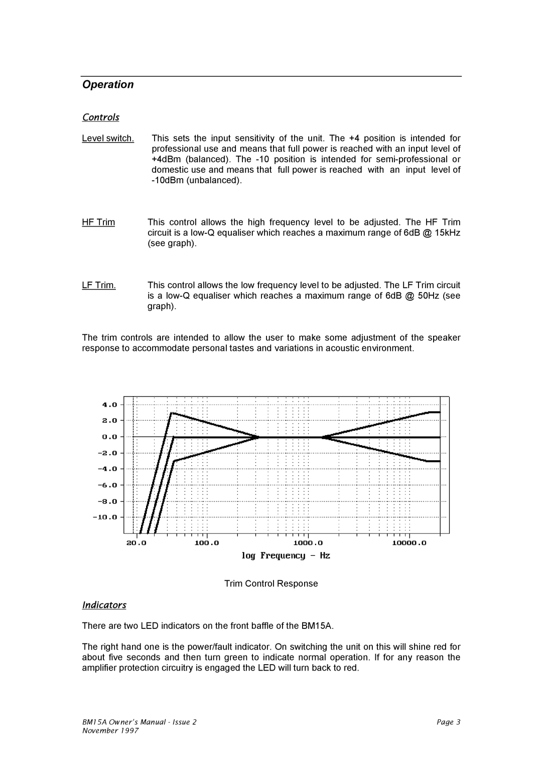
HF Trim | This control allows the high frequency level to be adjusted. The HF Trim |
| circuit is a |
| (see graph). |
LF Trim. | This control allows the low frequency level to be adjusted. The LF Trim circuit |
| is a |
| graph). |
The trim controls are intended to allow the user to make some adjustment of the speaker response to accommodate personal tastes and variations in acoustic environment.
Trim Control Response
Indicators
There are two LED indicators on the front baffle of the BM15A.
The right hand one is the power/fault indicator. On switching the unit on this will shine red for about five seconds and then turn green to indicate normal operation. If for any reason the amplifier protection circuitry is engaged the LED will turn back to red.
BM15A Owner’s Manual - Issue 2 | Page 3 |
November 1997 |
|