INSTALLATION
LED Indicators
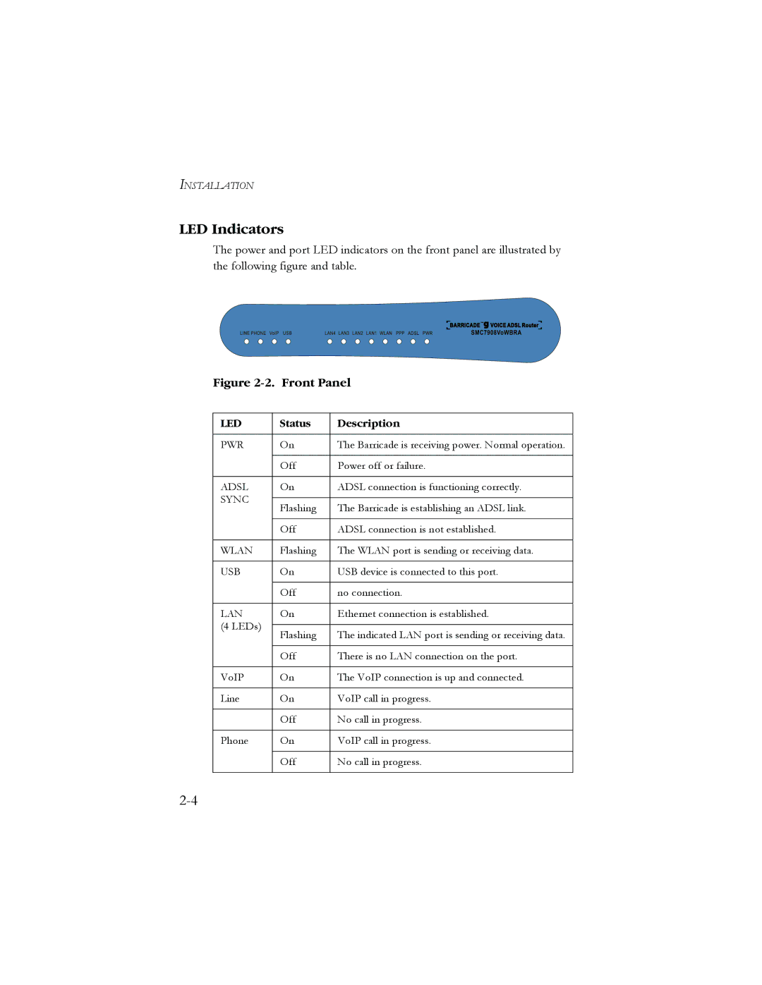
The power and port LED indicators on the front panel are illustrated by the following figure and table.
Figure 2-2. Front Panel
LED | Status | Description | |
|
|
| |
PWR | On | The Barricade is receiving power. Normal operation. | |
|
|
| |
| Off | Power off or failure. | |
|
|
| |
ADSL | On | ADSL connection is functioning correctly. | |
SYNC |
|
| |
Flashing | The Barricade is establishing an ADSL link. | ||
| |||
|
|
| |
| Off | ADSL connection is not established. | |
|
|
| |
WLAN | Flashing | The WLAN port is sending or receiving data. | |
|
|
| |
USB | On | USB device is connected to this port. | |
|
|
| |
| Off | no connection. | |
|
|
| |
LAN | On | Ethernet connection is established. | |
(4 LEDs) |
|
| |
Flashing | The indicated LAN port is sending or receiving data. | ||
| |||
|
|
| |
| Off | There is no LAN connection on the port. | |
|
|
| |
VoIP | On | The VoIP connection is up and connected. | |
|
|
| |
Line | On | VoIP call in progress. | |
|
|
| |
| Off | No call in progress. | |
|
|
| |
Phone | On | VoIP call in progress. | |
|
|
| |
| Off | No call in progress. | |
|
|
|