Dynex | 3 |
Setting up the switch
To set up the switch:
1Place the switch flat on a tabletop or use the enclosed screws to hang it ver- tically on a wall. Be sure to leave enough space around the switch for good ventilation.
2Don’t place heavy objects on the switch.
3Connect the AC power adapter to the switch, then plug the adapter into an AC power outlet. The switch turns on and initializes by blinking the Link/Act LEDs and turning on the Power LED.
4Connect your network cables to the switch.
Identifying switch components
Although the following illustrations show the
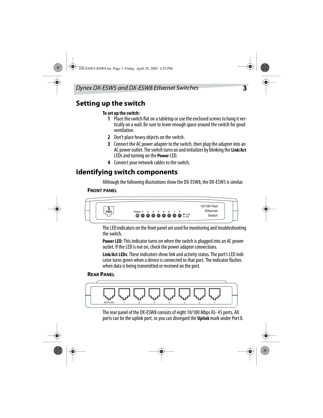
FRONT PANEL
The LED indicators on the front panel are used for monitoring and troubleshooting the switch.
Power LED: This indicator turns on when the switch is plugged into an AC power outlet. If the LED is not on, check the power adapter connections.
Link/Act LEDs: These indicators show link and activity status. The port’s LED indi- cator turns green when a device is connected to that port. The indicator flashes when data is being transmitted or received on the port.
REAR PANEL
The rear panel of the