IL05003022E.pdf
|
|
|
| Instruction sheet |
|
|
|
| |
|
|
|
| |
|
|
|
|
|
1 |
|
| WARNING | |
|
|
| ||
|
|
| and prevent electric shock or sudden collision on | |
|
|
| some special tool or key to open the enclosure, so as to avoid the hazard to users or any damage to the module. Do | |
|
|
| NOT touch terminals when power on. |
|
|
|
| I/O terminal screws should be tightened to between 1.95 | |
|
|
|
|
|
2 |
|
| INTRODUCTION | |
Environmental Specification:
Operation | 0℃~55℃(Temperature), 50~95%(Humidity), pollutant degree 2 |
|
|
Storage | |
|
|
Vibration/Shock resistance | International Standard: |
|
|
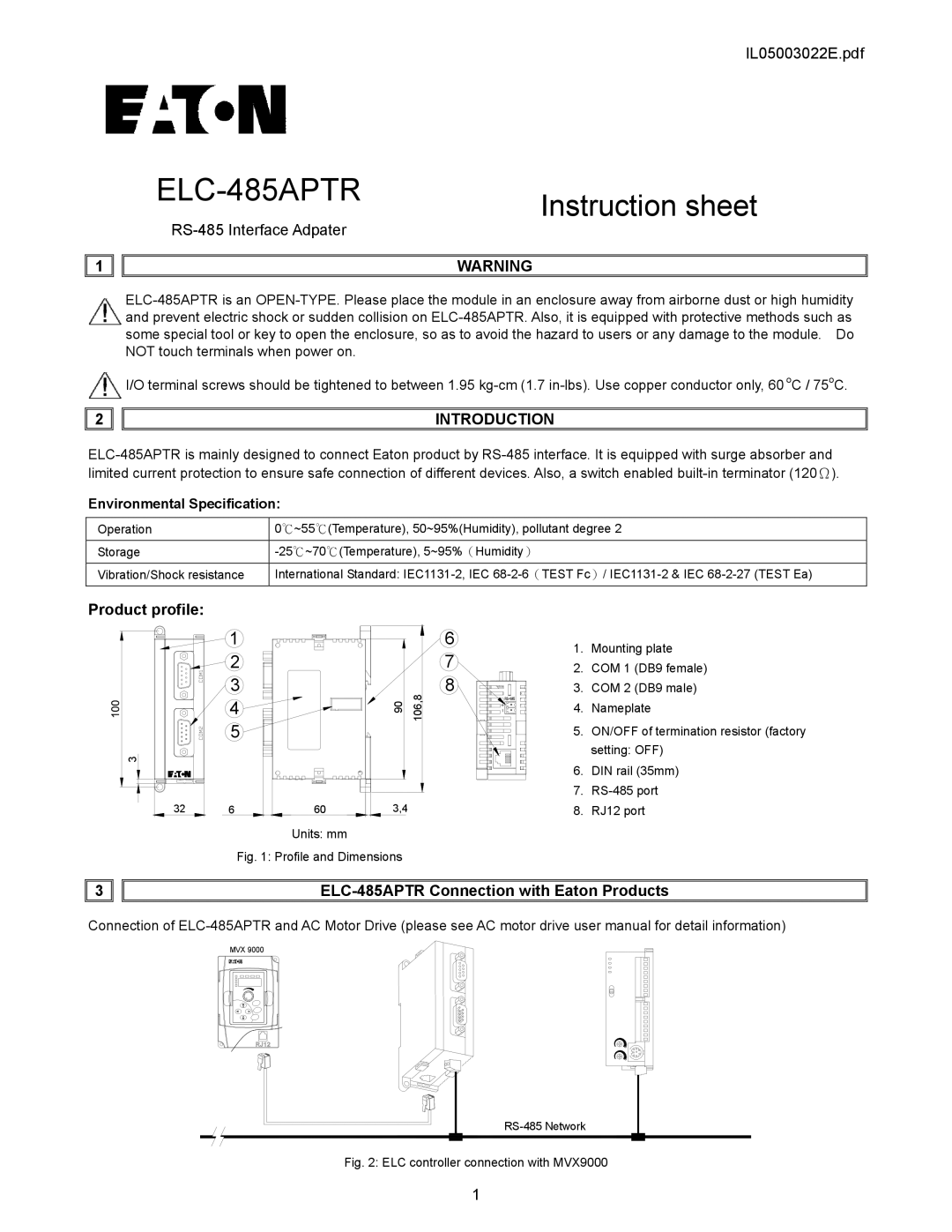
Product profile:
3
32
1 |
|
|
|
2 |
|
|
|
3 |
| 90 | 106,8 |
4 |
| ||
|
|
| |
5 |
|
|
|
6 | 60 | 3,4 |
|
Units: mm
Fig. 1: Profile and Dimensions
6
7
8
1.Mounting plate
2.COM 1 (DB9 female)
3.COM 2 (DB9 male)
4.Nameplate
5.ON/OFF of termination resistor (factory setting: OFF)
6.DIN rail (35mm)
7.RS-485 port
8.RJ12 port
3 |
|
|
Connection of
MVX 9000
Fig. 2: ELC controller connection with MVX9000
1
