IL05003022E.pdf
Compact Installation reference:
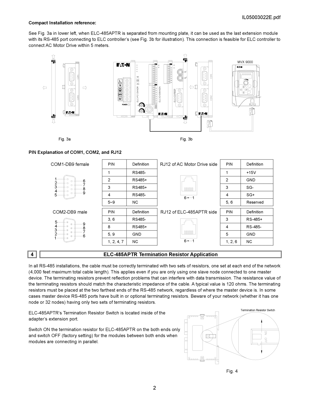
See Fig. 3a in lower left, when ELC-485APTR is separated from mounting plate, it can be used as the last extension module with its RS-485 port connecting to ELC controller’s (see Fig. 3b for illustration). This connection is feasible for ELC controller to connect AC Motor Drive within 5 meters.
MVX 9000
x161
x160
RS-485
RS-232
Fig. 3aFig. 3b
PIN Explanation of COM1, COM2, and RJ12 | | | | |
COM1-DB9 female | PIN | Definition | RJ12 of AC Motor Drive side | PIN | Definition |
| | 1 | RS485- | | 1 | +15V |
1 | 6 | 2 | RS485+ | | 2 | GND |
2 | 7 | | | | | |
3 | 3 | RS485+ | | 3 | SG- |
8 | |
4 | | | | | |
9 | 4 | RS485- | | 4 | SG+ |
5 | |
| |
| | 5~9 | NC | | 5, 6 | Reserved |
COM2-DB9 male | PIN | Definition | RJ12 of ELC-485APTR side | PIN | Definition |
5 | 9 | 3, 6 | RS485- | | 3 | RS-485+ |
| | | | |
4 | 8 | RS485+ | | 4 | RS-485- |
8 | |
3 | 7 | | | | | |
2 | 5, 9 | GND | | 5 | GND |
6 | |
1 | | | | | |
| 1, 2, 4, 7 | NC | | 1, 2, 6 | NC |
| | |
4 | | ELC-485APTR Termination Resistor Application | | |
In all RS-485 installations, the cable must be correctly terminated with two sets of resistors, one set at each end of the network (4,000 feet maximum total cable length). This applies even if you are only using one slave node connected to one master device. The terminating resistors prevent reflection problems that can interfere with data transmission. The resistance value of the terminating resistors should match the characteristic impedance of the cable. A typical value is 120 ohms. The terminating resistors must be placed at the two farthest ends of the RS-485 network, regardless of where the master device is. In some cases master device RS-485 ports have built in or optional terminating resistors. Beware of your network (whether it has one node or 32 nodes) having only two sets of terminating resistors.
ELC-485APTR’s Termination Resistor Switch is located inside of the adapter’s extension port.
Switch ON the termination resistor for ELC-485APTR on the both ends only and switch OFF (factory setting) for the modules between both ends when modules are connecting in parallel.
Termination Resistor Switch

