Magnum Transfer Switch specifications
The Eaton Electrical Magnum Transfer Switch is a premium solution designed for reliable power management in various applications, ranging from data centers to critical facilities. Known for its robust performance and advanced technology, the Magnum Transfer Switch ensures seamless transitions between utility and backup power sources, thereby enhancing operational continuity.One of the standout features of the Eaton Magnum Transfer Switch is its unparalleled reliability. The switch is designed with heavy-duty components that provide up to 3,000 amps of continuous current with exceptional fault protection. Its construction is particularly suited for environments where power availability is crucial, ensuring that critical loads remain powered even during grid failures.
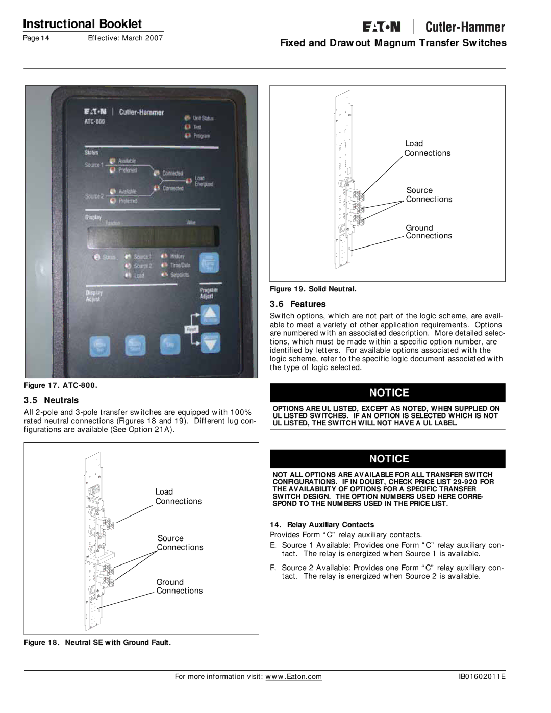
The Magnum Transfer Switch incorporates advanced technologies that simplify the operation and monitoring of power systems. It includes microprocessor-based controls that offer users customizable settings and configurations. These smart controls enable automatic transfer operations, ensuring quick response times when switching between power sources. The intelligent diagnostics feature further enhances reliability by offering predictive maintenance alerts, which help in identifying potential issues before they lead to failures.
Safety is a priority with the Magnum Transfer Switch. It is equipped with multiple interlocking features that prevent accidental switchovers and ensure that maintenance can be performed without the risk of electrical accidents. The design adheres to stringent safety standards, providing users with peace of mind.
Flexibility is another characteristic of the Eaton Magnum Transfer Switch. It offers a range of mounting options and configurations to fit diverse installation needs, whether in commercial infrastructures or industrial settings. The switch can be integrated with various power systems, making it a versatile choice for project developers and facility managers.
Additionally, the Magnum Transfer Switch supports eco-friendly initiatives through energy-efficient designs that minimize power loss during transfer operations. This feature is increasingly important as businesses aim to reduce their carbon footprint and enhance sustainability.
In summary, the Eaton Electrical Magnum Transfer Switch stands out for its reliable performance, advanced technologies, and robust safety measures. It is a versatile solution that meets the demands of modern power management, ensuring that critical systems operate continuously, even in the face of unexpected power interruptions. With its combination of efficiency, safety, and flexibility, the Magnum Transfer Switch remains a trusted choice for professionals in various industries.

