MN05401014E:MN05401014E 2/9/07 1:27 PM Page 4
7. Contents
1 Digital display
1 Panel mounting clip
1 Bezel for screw mounting, panel cut out
50 x 25 mm [1.97 x 0.98 in.]
1 Bezel for clip mounting, panel cut out
50 x 25 mm [1.97 x 0.98 in.]
1Seal
1Multilingual operating instructions
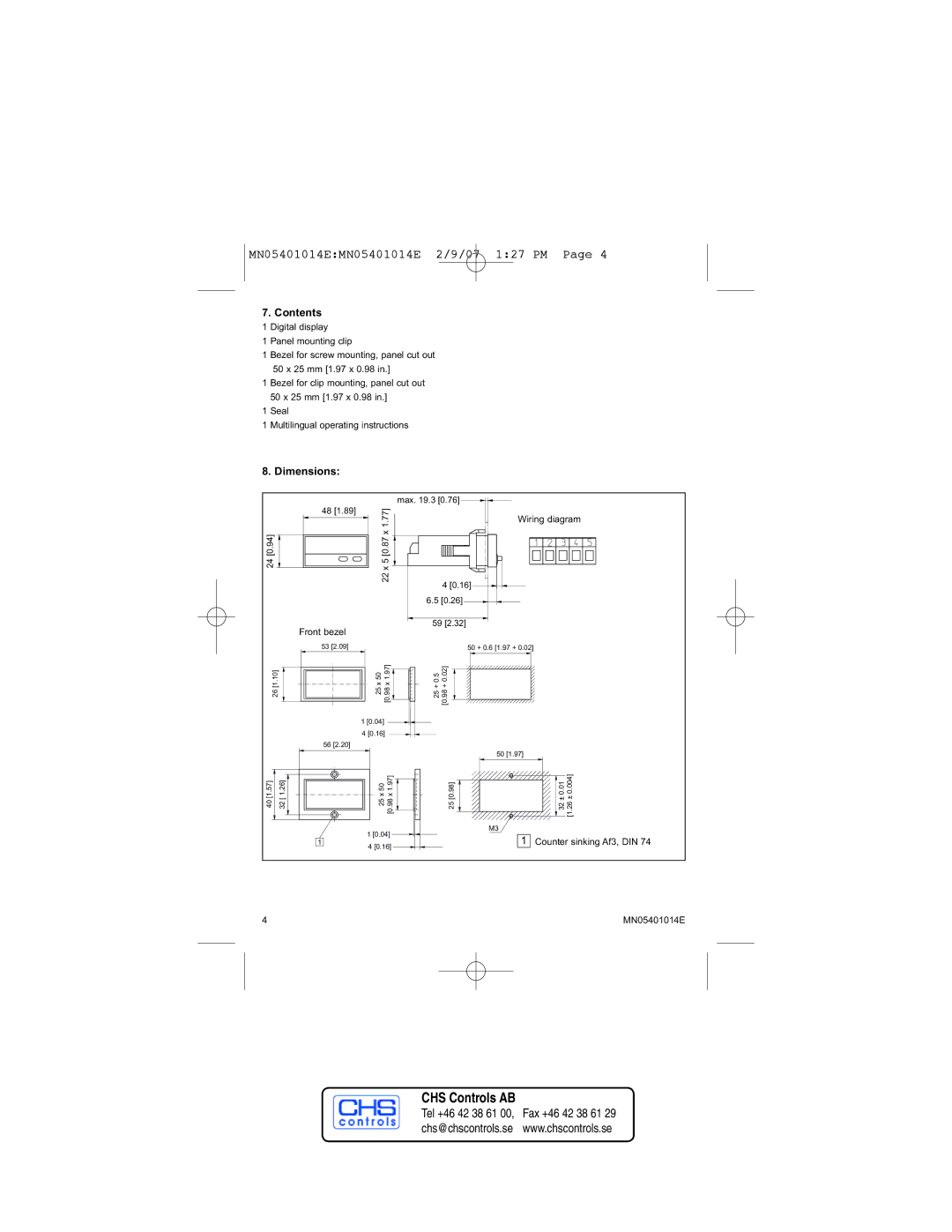
8. Dimensions:
| 48 [1.89] |
[0.94] | [0.87 x1.77] |
24 | x 5 |
| 22 |
| Front bezel | |||
| 53 [2.09] |
|
| |
26[1.10] |
|
|
| 25 x 50 [0.98 x 1.97] |
|
|
| ||
|
|
| ||
|
|
| ||
| 1 [0.04] | |||
4 [0.16]
56 [2.20]
max. 19.3 [0.76]
Wiring diagram
4[0.16]
6.5[0.26]
59 [2.32]
50 + 0.6 [1.97 + 0.02]
25 + 0.5 [0.98 + 0.02]
50 [1.97]
40 [1.57] | 32 [ 1.26] |
| 25 x 50 [0.98 x 1.97] |
|
|
| 1 [0.04] |
|
| 1 | 4 [0.16] |
|
|
|
25 [0.98]
M3
1
32 ± 0.01 [1.26 ± 0.004]
Counter sinking Af3, DIN 74
4 | MN05401014E |