IL01301016E
DISCLAIMER OF WARRANTIES AND LIMITATION OF LIABILITY
The information, recommendations, descriptions and safety notations in this document are based on Eaton Electrical Inc. and/or Eaton Corporation’s (“Eaton”) experience and judgment and may not cover all contingencies. If further information is required, an Eaton sales office should be consulted.
Sale of the product shown in this literature is subject to the terms and condi- tions outlined in appropriate Eaton selling policies or other contractual agree- ment between Eaton and the purchaser.
IL01301016E
Installation and Removal Instructions for Series NRX Drawout |
|
Cassette Primary Adapters |
|
Table of Contents |
|
Description | Page |
Section 1: General Information | . . . 1 |
Section 2: Rear Mounted Connections | . . . 2 |
THERE ARE NO UNDERSTANDINGS, AGREEMENTS, WARRANTIES, EXPRESSED OR IMPLIED, INCLUDING WARRANTIES OF FITNESS FOR A PAR- TICULAR PURPOSE OR MERCHANTABILITY, OTHER THAN THOSE SPECIFICAL- LY SET OUT IN ANY EXISTING CONTRACT BETWEEN THE PARTIES. ANY SUCH CONTRACT STATES THE ENTIRE OBLIGATION OF EATON. THE CON- TENTS OF THIS DOCUMENT SHALL NOT BECOME PART OF OR MODIFY ANY CONTRACT BETWEEN THE PARTIES.
In no event will Eaton be responsible to the purchaser or user in contract, in tort (including negligence), strict liability or otherwise for any special, indirect, incidental or consequential damage or loss whatsoever, including but not limit- ed to damage or loss of use of equipment, plant or power system, cost of capi- tal, loss of power, additional expenses in the use of existing power facilities, or claims against the purchaser or user by its customers resulting from the use of the information, recommendations and descriptions contained herein.
The information contained in this manual is subject to change without notice.
(1)Only qualified electrical per- sonnel should be permitted to work on the equipment.
(2)Always
(3)Drawout circuit breakers should should be levered (racked) out to the Disconnect position.
(4)All circuit breakers should be switched to the off position and mechanism springs discharged.
Failure to follow these steps for all procedures described in this instruction leaflet could result in death, bodily injury, or property damage.
Section 1: General
Information
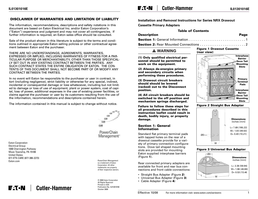
Figure 1 Drawout Cassette (rear view)
Interphase |
Barrier |
Dove Tail |
Mounting |
Slots |
Primary |
Terminal |
Pads |
Interphase |
Barrier |
Dove Tail |
Mounting |
Slots |
Figure 2 Straight Bus Adapter
Dimensions |
inches [mm] |
L |
L= 7.69 [195.22] |
W= 1.93 [49.02] |
Eaton Corporation
Electrical Group
1000 Cherrington Parkway
Moon Township, PA 15108
United States
Eaton.com
PowerChain Management is a trademark of Eaton Corporation. All other trademarks are property of their respective owners.
© 2008 Eaton Corporation
All Rights Reserved
Printed in USA
Publication No. IL01301016E
October 2008
Standard flat primary terminal pads with tapped holes on the rear of a drawout cassette provide for a vari- ety of primary connection configura- tions. Dove tail shaped mounting slots are provided for mounting Eaton supplied interphase barriers (Figure 1).
Rear connected primary adapters are available for front and rear bus con- nections and front cable connections:
•Straight Bus Adapter (Figure 2)
•Universal Bus Adapter (Figure 3)
•Cable Adapter (Figure 4)
ØD | D= 0.40 [10.21] |
|
W
Figure 3 Universal Bus Adapter
![]() ØD
ØD![]()
Dimensions
inches [mm]
L= 2.36 [59.94]
W= 1.96 [49.68]
D= 0.53 [13.46
LW
Effective 10/08 | For more information visit: www.eaton.com/seriesnrx | 1 |