IL01301016E
IL01301016E
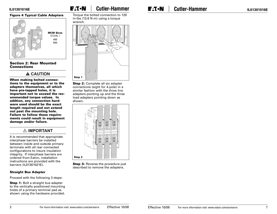
Figure 4 Typical Cable Adapters
MCM Sizes |
(CU/AL ) |
400 |
500 |
Section 2: Rear Mounted Connections
When making bolted connec- tions to the equipment or to the adapters themselves, all which have
It is recommended that appropriate interphase barriers be installed between inside and outside primary terminals with all rear connected configurations to insure insulation integrity. If interphase barriers are ordered from Eaton, installation instructions are provided with the barriers (IL01301021E).
Straight Bus Adapter
Proceed with the following 3 steps:
Step 1: Bolt a straight bus adapter to the vertically positioned mounting holes of a primary terminal pad as shown using the hardware provided.
Torque the bolted connection to 120
Step 1 |
Step 2: Complete all six adapter connections (eight for
Step 2 |
Step 3: Reverse the procedure just described to remove the adapters.
2 | For more information visit: www.eaton.com/seriesnrx | Effective 10/08 |
Effective 10/08 | For more information visit: www.eaton.com/seriesnrx | 7 |