Instructions/Installing the KF850z
NL8 and AP6 Upgrade Kits
The KF850z AP6 Upgrade Kit P/N 0006241 and the KF850z NL8 Upgrade Kit P/N 0006242 are available for the KF850e loudspeaker. These two kits are the same but for the Electrical Assemblies.
Warning: Installation should only be done by an experienced technician. Improper installation may result in damage to the equipment, injury or death.
1.Inventory the kit against the following bill of materials insuring the kit is complete.
EAW P/N | Qty | Description |
804116 | 1 | |
102021 | 4 | Screw |
0005848 | 1 | Horn/URE/H4532 |
0008726 | 1 | Driver/Compression |
102165 | 4 | Screw/M6 X 14mm LG HHCS |
105005 | 4 | Washer/Flat 1/4 |
105004 | 8 | Washer/Lock 1/4 |
0006004 | 2 | Bracket/Horn [KF850z Upgrade Kit] |
102016 | 6 | Screw |
105007 | 10 | Washer/Flat 1/4 Blk |
105008 | 10 | Washer/Lock 1/4 Blk |
102017 | 4 | Screw |
804097 | 1 | |
0006008 | 1 | Assembly/Phase Plug/Housing |
0006005 | 1 | Ring/Aperture/Wood/10” Mid [KF850z] |
0006007 | 4 | Screw |
105033 | 4 | Washer/Flat/M6 |
0006011 | 1 | Instruction/Kit/KF850z/Upgrade |
102087 | 4 | Screw #8 X 1 LG PH PHSMS |
102048 | 8 | Screw #10 X 16 X 3/4 PH PHSMS |
102102 | 23 | Screw #8 X 5/8 PH PHSMS Blk |
0006239 | 1 | Electrical Assembly KF850z [NL8] |
or |
|
|
0006240 | 1 | Electrical Assembly KF850z [AP6] |
2.Overview
KF850z Kit installation requires the technician to remove and replace all transducer components. The HF horn assembly is accessed from the front and the 15” woofer, 10” mid range, and electrical assembly from
the back.
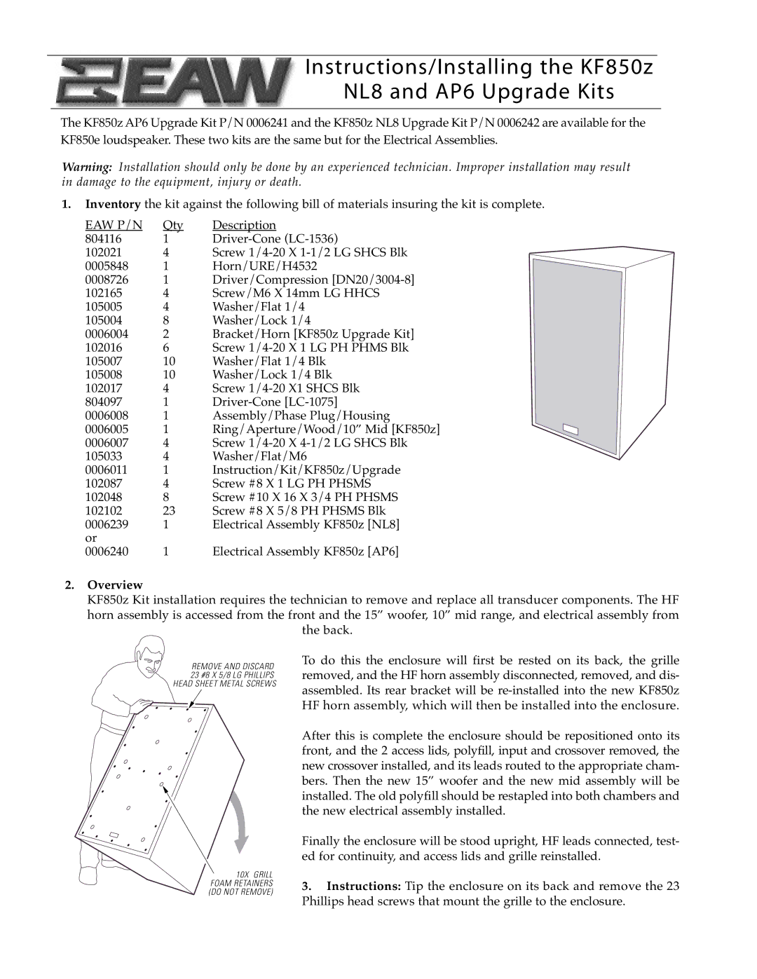
REMOVE AND DISCARD 23 #8 X 5/8 LG PHILLIPS HEAD SHEET METAL SCREWS
10X GRILL FOAM RETAINERS (DO NOT REMOVE)
To do this the enclosure will first be rested on its back, the grille removed, and the HF horn assembly disconnected, removed, and dis- assembled. Its rear bracket will be
After this is complete the enclosure should be repositioned onto its front, and the 2 access lids, polyfill, input and crossover removed, the new crossover installed, and its leads routed to the appropriate cham- bers. Then the new 15” woofer and the new mid assembly will be installed. The old polyfill should be restapled into both chambers and the new electrical assembly installed.
Finally the enclosure will be stood upright, HF leads connected, test- ed for continuity, and access lids and grille reinstalled.
3.Instructions: Tip the enclosure on its back and remove the 23 Phillips head screws that mount the grille to the enclosure.