US O C A
T
|
|
|
| ORMA |
|
|
| |
|
|
| RF | N |
|
| ||
|
| E |
|
| CE |
| ||
| P |
|
|
|
| P | ||
| L |
|
|
|
|
|
| A |
A |
|
|
|
|
|
| T | |
IC |
|
|
|
|
|
|
| R |
|
|
|
|
|
|
| N | |
|
|
|
|
|
|
|
| E |
|
|
|
|
|
|
|
| R |
|
|
|
|
|
|
|
| S |
|
|
|
|
|
|
|
| H |
|
|
|
|
|
|
|
| I |
|
|
|
|
|
|
|
| P |
TECHNICAL SPECIFICATIONS MQ1364
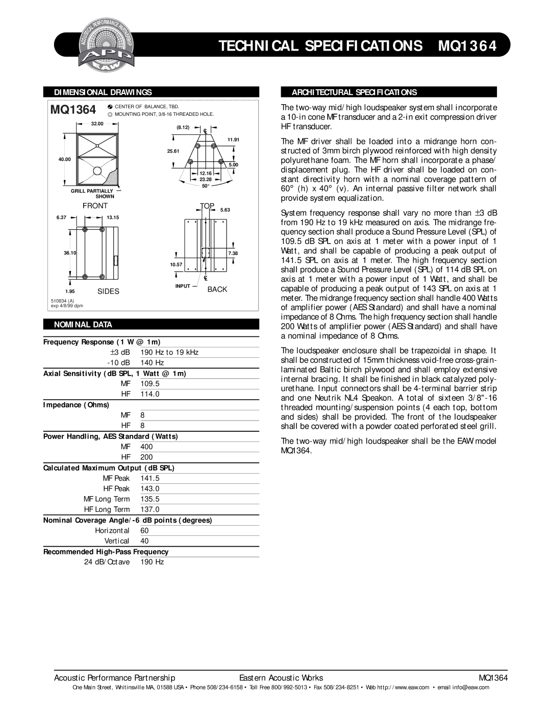
DIMENSIONAL DRAWINGS
MQ1364 | CENTER OF BALANCE, TBD. |
MOUNTING POINT, |
32.00 | (8.12) |
|
|
| |
| C |
|
| L |
|
|
| 11.91 |
| 25.61 |
|
40.00 |
| 5.00 |
|
| |
| 12.16 |
|
| 23.28 |
|
GRILL PARTIALLY | 50° |
|
|
| |
SHOWN |
|
|
FRONT | TOP | 5.63 |
6.37 | 13.15 |
|
|
36.10 |
|
| 7.38 |
|
| 10.57 |
|
|
|
| C |
|
|
| L |
1.95 | SIDES | INPUT | BACK |
| |||
510834 (A) |
|
|
|
exp 4/8/99 dpm |
|
|
|
NOMINAL DATA |
|
| |
Frequency Response (1 W @ 1m) |
| ||
| ±3 dB | 190 Hz to 19 kHz |
|
| 140 Hz |
| |
Axial Sensitivity (dB SPL, 1 Watt @ 1m)
MF 109.5
HF 114.0
Impedance (Ohms)
MF 8
HF 8
Power Handling, AES Standard (Watts)
MF 400
HF 200
Calculated Maximum Output (dB SPL)
MF Peak | 141.5 |
HF Peak | 143.0 |
MF Long Term | 135.5 |
HF Long Term | 137.0 |
Nominal Coverage
Horizontal 60
Vertical 40
Recommended
24 dB/Octave 190 Hz
ARCHITECTURAL SPECIFICATIONS
The
The MF driver shall be loaded into a midrange horn con- structed of 3mm birch plywood reinforced with high density polyurethane foam. The MF horn shall incorporate a phase/ displacement plug. The HF driver shall be loaded on con- stant directivity horn with a nominal coverage pattern of 60° (h) x 40° (v). An internal passive filter network shall provide system equalization.
System frequency response shall vary no more than ±3 dB from 190 Hz to 19 kHz measured on axis. The midrange fre- quency section shall produce a Sound Pressure Level (SPL) of
109.5dB SPL on axis at 1 meter with a power input of 1 Watt, and shall be capable of producing a peak output of
141.5SPL on axis at 1 meter. The high frequency section shall produce a Sound Pressure Level (SPL) of 114 dB SPL on axis at 1 meter with a power input of 1 Watt, and shall be capable of producing a peak output of 143 SPL on axis at 1 meter. The midrange frequency section shall handle 400 Watts of amplifier power (AES Standard) and shall have a nominal impedance of 8 Ohms. The high frequency section shall handle 200 Watts of amplifier power (AES Standard) and shall have a nominal impedance of 8 Ohms.
The loudspeaker enclosure shall be trapezoidal in shape. It shall be constructed of 15mm thickness
The
Acoustic Performance Partnership | Eastern Acoustic Works | MQ1364 |
One Main Street, Whitinsville MA, 01588 USA • Phone