Horn Rotation Instructions
•The
1.Using a medium phillips screwdriver, remove the 18 screws attaching the grille to the enclosure, and gently remove the grille. Do not remove the foam grille backing.
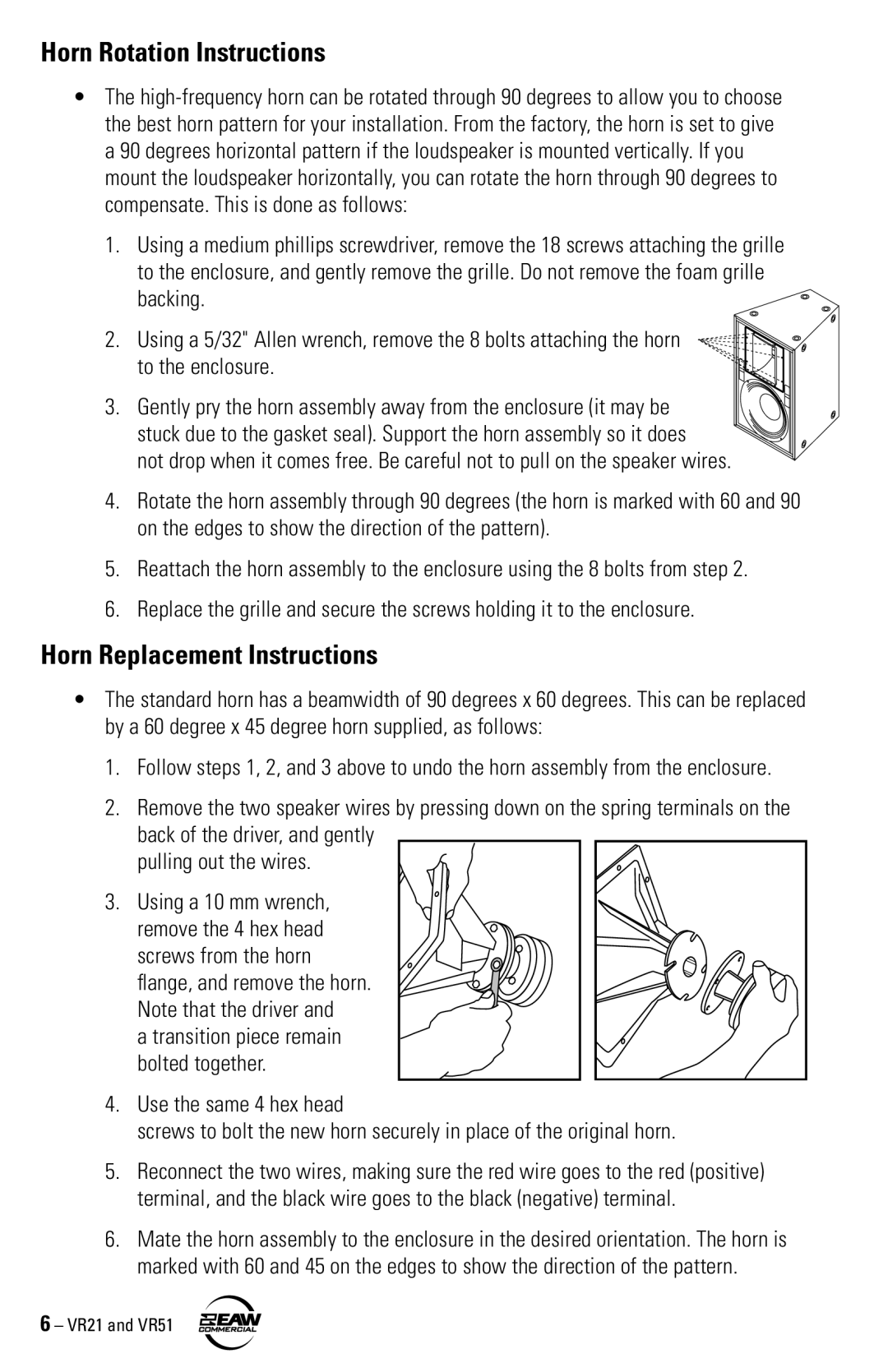
2.Using a 5/32" Allen wrench, remove the 8 bolts attaching the horn
to the enclosure.
3. Gently pry the horn assembly away from the enclosure (it may be stuck due to the gasket seal). Support the horn assembly so it does
not drop when it comes free. Be careful not to pull on the speaker wires.
4.Rotate the horn assembly through 90 degrees (the horn is marked with 60 and 90 on the edges to show the direction of the pattern).
5.Reattach the horn assembly to the enclosure using the 8 bolts from step 2.
6.Replace the grille and secure the screws holding it to the enclosure.
Horn Replacement Instructions
•The standard horn has a beamwidth of 90 degrees x 60 degrees. This can be replaced by a 60 degree x 45 degree horn supplied, as follows:
1.Follow steps 1, 2, and 3 above to undo the horn assembly from the enclosure.
2.Remove the two speaker wires by pressing down on the spring terminals on the back of the driver, and gently
pulling out the wires.
3.Using a 10 mm wrench, remove the 4 hex head screws from the horn flange, and remove the horn. Note that the driver and
a transition piece remain bolted together.
4.Use the same 4 hex head
screws to bolt the new horn securely in place of the original horn.
5.Reconnect the two wires, making sure the red wire goes to the red (positive) terminal, and the black wire goes to the black (negative) terminal.
6.Mate the horn assembly to the enclosure in the desired orientation. The horn is marked with 60 and 45 on the edges to show the direction of the pattern.
