7.Install the horn assembly to the enclosure using the 8 Allen bolts.
8.Replace the grille and secure the screws holding it to the enclosure.
4.CONNECTIONS
WARNING: To prevent the risk of electric shock, do not connect the loudspeaker with the amplifier switched on. The protective cover over the terminal strip is a safety
feature per CE requirements. Replace this cover after making the signal connections.
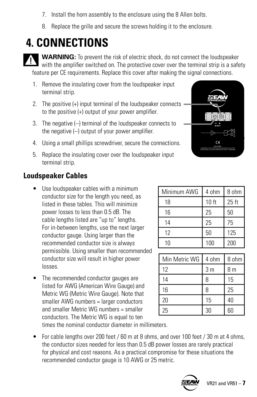
1.Remove the insulating cover from the loudspeaker input terminal strip.
2.The positive (+) input terminal of the loudspeaker connects to the positive (+) output of your power amplifier.
3.The negative
4.Using a small phillips screwdriver, secure the connections.
5.Replace the insulating cover over the loudspeaker input terminal strip.
--+
IN PUT
HF
AMP | XVR |
LF
CAUTION:
SUSPENDING THIS SYSTEM SHOULD BE DONE BY QUALIFIED TECHNICIANS FOLLOWING APPROPRIATE SAFETY STANDARDS
Loudspeaker Cables
• Use loudspeaker cables with a minimum |
|
|
| |
Minimum AWG | 4 ohm | 8 ohm | ||
conductor size for the length you need, as | ||||
18 | 10 ft | 25 ft | ||
listed in these tables. This will minimize | ||||
power losses to less than 0.5 dB. The | 16 | 25 | 50 | |
cable lengths listed are “up to” lengths. |
|
|
| |
14 | 25 | 75 | ||
For | ||||
12 | 50 | 125 | ||
conductor gauge. Using larger than the | ||||
recommended conductor size is always | 10 | 100 | 200 | |
permissible. Using smaller than recommended |
|
|
| |
|
|
| ||
conductor size will result in higher power | Min Metric WG | 4 ohm | 8 ohm | |
losses. |
|
|
| |
12 | 3 m | 8 m | ||
| ||||
• The recommended conductor gauges are | 14 | 8 | 15 | |
listed for AWG (American Wire Gauge) and |
|
|
| |
16 | 8 | 25 | ||
Metric WG (Metric Wire Gauge). Note that | ||||
20 | 15 | 40 | ||
smaller AWG numbers = larger conductors | ||||
and smaller Metric WG numbers = smaller | 25 | 30 | 60 | |
conductors. The Metric WG is equal to ten |
|
|
|
times the nominal conductor diameter in millimeters.
• For cable lengths over 200 feet / 60 m at 8 ohms, and over 100 feet / 30 m at 4 ohms, the conductor sizes needed for less than 0.5 dB power losses are rarely practical for physical and cost reasons. As a practical compromise for these situations the recommended conductor gauge is 10 AWG or 25 metric.