
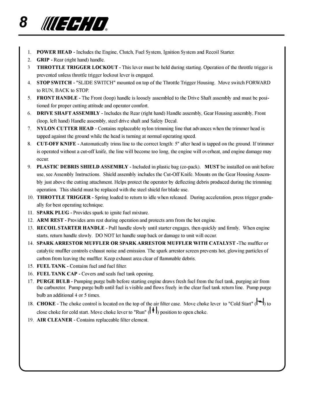
SRM-280S, SRM-280 specifications
The Echo SRM-280 and SRM-280S are robust and versatile string trimmers designed for both residential and commercial use. These trimmers are part of Echo's reputation for producing reliable, high-quality outdoor power equipment, and they have gained recognition in the landscaping industry due to their powerful performance and ease of use.One of the standout features of the SRM-280 is its professional-grade 28.1cc engine. This powerful engine delivers impressive power, making it suitable for tackling the toughest vegetation. The SRM-280S variant comes with a slightly differentiated design, boasting added features such as easier starting mechanisms and user-friendly controls that enhance the overall user experience.
A key aspect of these models is their lightweight design. Weighing in at around 11.2 pounds, they are easy to maneuver for extended periods without undue fatigue. This makes them ideal for both homeowners and landscape professionals who may need to use the trimmers for hours on end. The ergonomic design of the handle further enhances comfort during operation, allowing for better control and precision when trimming.
A notable technology integrated into both models is Echo's Load-Shift Technology, which allows for efficient cutting by optimizing the engine's performance based on the load. This means that as the user encounters thicker grass or weeds, the engine adjusts to maintain power without stalling. The result is increased efficiency and a cleaner cut.
Both the SRM-280 and SRM-280S come equipped with a durable, dual-line cutting head that is easy to reload. The 0.095-inch cutting line offers an ideal balance of durability and cutting efficiency, allowing users to tackle tougher jobs without worrying about line wear. Additionally, the head design minimizes line tangling, further streamlining the trimming process.
Fuel efficiency is another highlight, as both trimmers boast a significant reduction in emissions thanks to Echo's advanced 2-stroke engine technology. This makes them a more environmentally-friendly choice compared to some older models, aligning with the growing demand for greener equipment.
In summary, the Echo SRM-280 and SRM-280S string trimmers provide users with a combination of power, efficiency, and user-centric design. With their professional-grade engines, lightweight construction, and advanced technology features, these trimmers stand out as reliable tools for anyone looking to maintain pristine lawns and landscapes. Whether for commercial or residential purposes, they offer unmatched performance and ease of use, making them a worthwhile investment for any landscaping endeavor.