INSTALLATION PROCEDURE
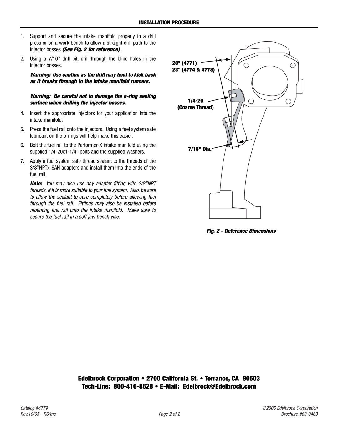
1.Support and secure the intake manifold properly in a drill press or on a work bench to allow a straight drill path to the injector bosses (See Fig. 2 for reference).
2.Using a 7/16” drill bit, drill through the blind holes in the injector bosses.
Warning: Use caution as the drill may tend to kick back as it breaks through to the intake manifold runners.
Warning: Be careful not to damage the
4.Insert the appropriate injectors for your application into the intake manifold.
5.Press the fuel rail onto the injectors. Using a fuel system safe lubricant on the
6.Bolt the fuel rail to the
7.Apply a fuel system safe thread sealant to the threads of the
Note: You may also use any adapter fitting with 3/8”NPT threads, if it is more suitable to your fuel system. Also, be sure to allow the sealant to cure completely before allowing fuel through the fuel rail. Fittings may also be installed before mounting fuel rail onto the intake manifold. Make sure to secure the fuel rail in a soft jaw bench vise.
20° (4771)  23° (4774 & 4778)
1/4-20  (Coarse Thread)
7/16” Dia.
Fig. 2 - Reference Dimensions
Edelbrock Corporation • 2700 California St. • Torrance, CA 90503
Catalog #4779 |
| ©2005 Edelbrock Corporation |
Rev.10/05 - RS/mc | Page 2 of 2 | Brochure |