brown: live
blue: neutral
The wire which is coloured blue must be connected to the terminal/wire which is marked with the letter N or coloured black.
The wire which is coloured brown must be connected to the terminal/wire which is marked with the letter L or coloured red.
The apparatus is not to be earthed, so no connection is to be made to terminals or wires marked with the letter E, the sym-
bol ![]() or coloured green or green and yellow.
or coloured green or green and yellow.
Bring the low voltage wiring from the control panel to where the smoke alarm is to be located. Route all wires neatly and securely along the walls and ceilings.
Note: Turning off the power switch on the Control Panel does not switch off the apparatus from the supply mains. The switch removes the AC and battery power from the Control Panel, but the mains transformer remains connected to the supply mains.
Vibration Pad
Plug the vibration pad into its locking socket on the control panel. Place the vibration pad under the pillow or mattress. It is important that the person in the bed can feel the vibration - check it is sufficient to wake a person by lying on the bed and pressing the test button on the control panel - see also “Test- ing your system”. Some mattresses may not transmit suffi- cient vibration, and in these cases it should be fitted under the pillow. Note: During testing, or in an actual alarm situation, the pad pulses on and off for greater effect on sleepers.
Mains Smoke Alarm Interface Pattress Ei 172/160
3.The low voltage wiring from the control panel must not be run in the same conduit as the mains/interconnect wires.
4.Using a sharp knife remove material from the appropriate knockouts making sure that there is no gap, either where mated with the ducting/conduit or with the low voltage wires. There are three knockouts and one on the rear.
5.Screw the pattress to the surface using the two screws and plastic plugs supplied.
6.Figure 1 shows the connections. Connect the incoming live, neutral, and interconnect (from other smoke alarms if present) to the
Connect the red wire (remove the small piece of insulating tape first) from the control panel to the terminal marked “R” and the yellow wire to the terminal marked “Y”. The black and blue wires from the control panel are not used. They should both be connected to the spare terminal for extra strain relief.
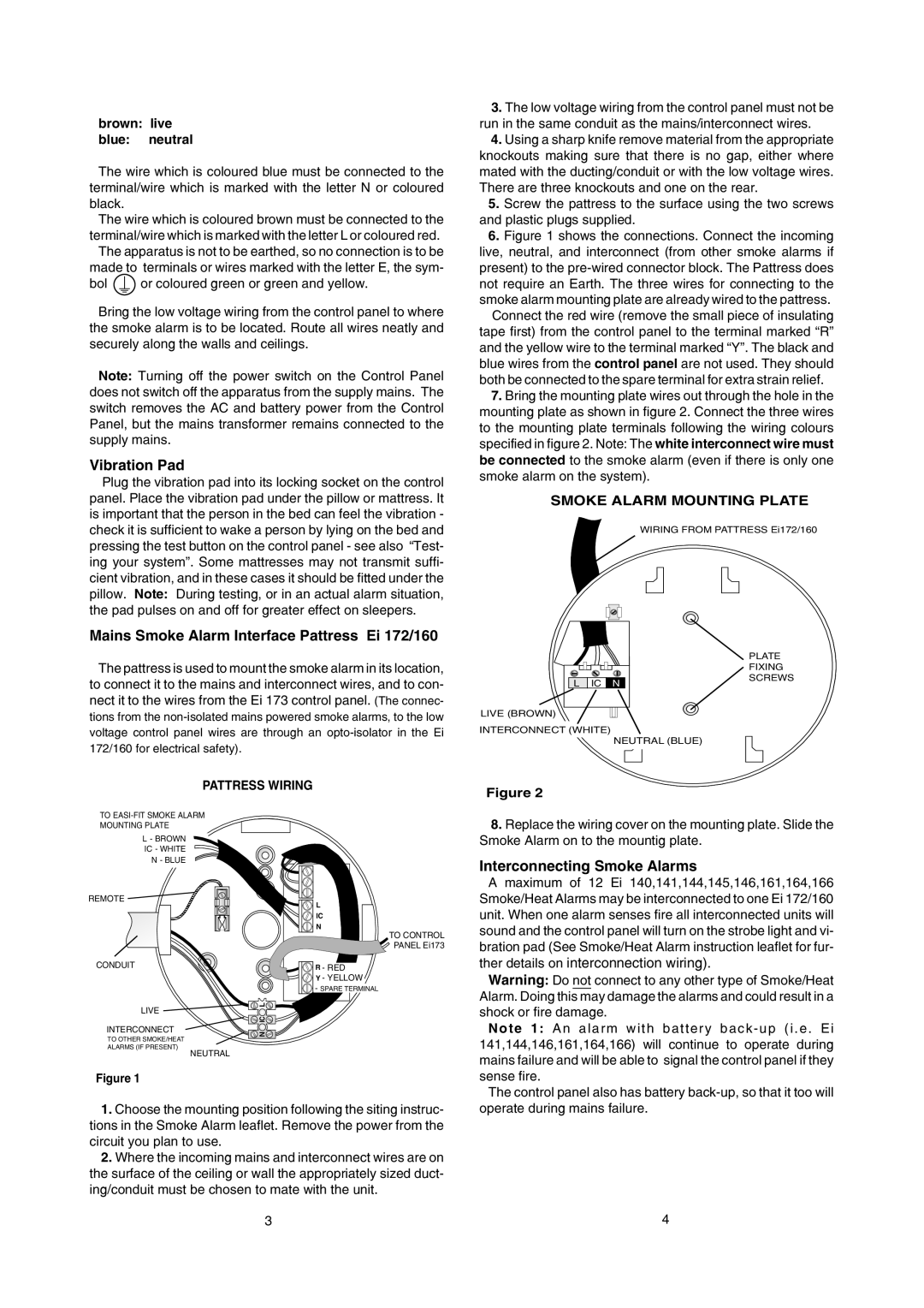
7.Bring the mounting plate wires out through the hole in the mounting plate as shown in figure 2. Connect the three wires to the mounting plate terminals following the wiring colours specified in figure 2. Note: The white interconnect wire must be connected to the smoke alarm (even if there is only one smoke alarm on the system).
SMOKE ALARM MOUNTING PLATE
WIRING FROM PATTRESS Ei172/160
The pattress is used to mount the smoke alarm in its location, to connect it to the mains and interconnect wires, and to con- nect it to the wires from the Ei 173 control panel. (The connec- tions from the
L IC N
LIVE (BROWN)
INTERCONNECT (WHITE)
PLATE
FIXING SCREWS
172/160 for electrical safety).
NEUTRAL (BLUE)
PATTRESS WIRING
Figure 2
TO
MOUNTING PLATE
L- BROWN IC - WHITE N - BLUE
REMOTE
CONDUIT
LIVE
INTERCONNECT
TO OTHER SMOKE/HEAT
ALARMS (IF PRESENT)
NEUTRAL
Figure 1
![]() L
L ![]()
![]() IC
IC ![]()
![]() N
N ![]()
L
IC
![]()
![]() N
N
TO CONTROL
PANEL Ei173
![]() R - RED
R - RED
![]() Y - YELLOW
Y - YELLOW
![]()
![]()
![]() - SPARE TERMINAL
- SPARE TERMINAL
8.Replace the wiring cover on the mounting plate. Slide the Smoke Alarm on to the mountig plate.
Interconnecting Smoke Alarms
A maximum of 12 Ei 140,141,144,145,146,161,164,166 Smoke/Heat Alarms may be interconnected to one Ei 172/160 unit. When one alarm senses fire all interconnected units will sound and the control panel will turn on the strobe light and vi- bration pad (See Smoke/Heat Alarm instruction leaflet for fur- ther details on interconnection wiring).
Warning: Do not connect to any other type of Smoke/Heat Alarm. Doing this may damage the alarms and could result in a shock or fire damage.
N o t e 1 : A n a l a r m w i t h b a t t e r y b a c k - u p ( i . e . E i 141,144,146,161,164,166) will continue to operate during mains failure and will be able to signal the control panel if they sense fire.
1.Choose the mounting position following the siting instruc- tions in the Smoke Alarm leaflet. Remove the power from the circuit you plan to use.
2.Where the incoming mains and interconnect wires are on the surface of the ceiling or wall the appropriately sized duct- ing/conduit must be chosen to mate with the unit.
3
The control panel also has battery
4