w w w . e l a t i o n l i g h t i n g . c o m
O V E R V I E W
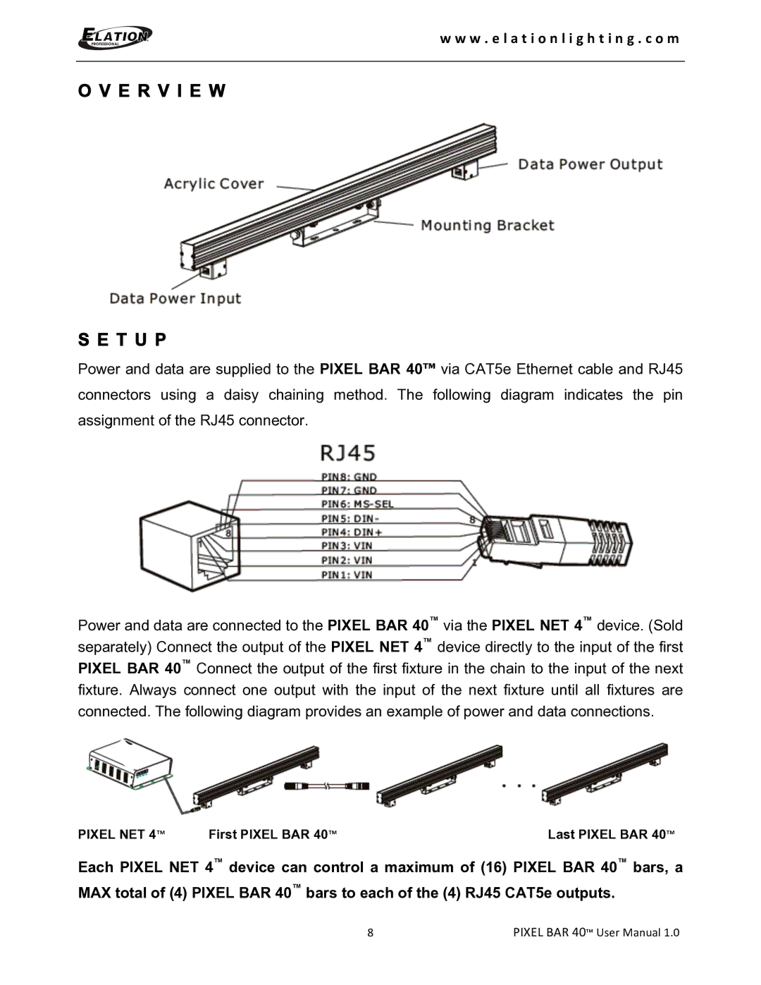
S E T U P
Power and data are supplied to the PIXEL BAR 40™ via CAT5e Ethernet cable and RJ45
connectors using a daisy chaining method. The following diagram indicates the pin
assignment of the RJ45 connector.
Power and data are connected to the PIXEL BAR 40™ via the PIXEL NET 4™ device. (Sold separately) Connect the output of the PIXEL NET 4™ device directly to the input of the first PIXEL BAR 40™ Connect the output of the first fixture in the chain to the input of the next fixture. Always connect one output with the input of the next fixture until all fixtures are connected. The following diagram provides an example of power and data connections.
PIXEL NET 4™ | First PIXEL BAR 40™ | Last PIXEL BAR 40™ |
Each PIXEL NET 4™ device can control a maximum of (16) PIXEL BAR 40™ bars, a MAX total of (4) PIXEL BAR 40™ bars to each of the (4) RJ45 CAT5e outputs.
8 | PIXEL BAR 40™ User Manual 1.0 |