Frequency Response:
Architects’ and Engineers’
Specifications:
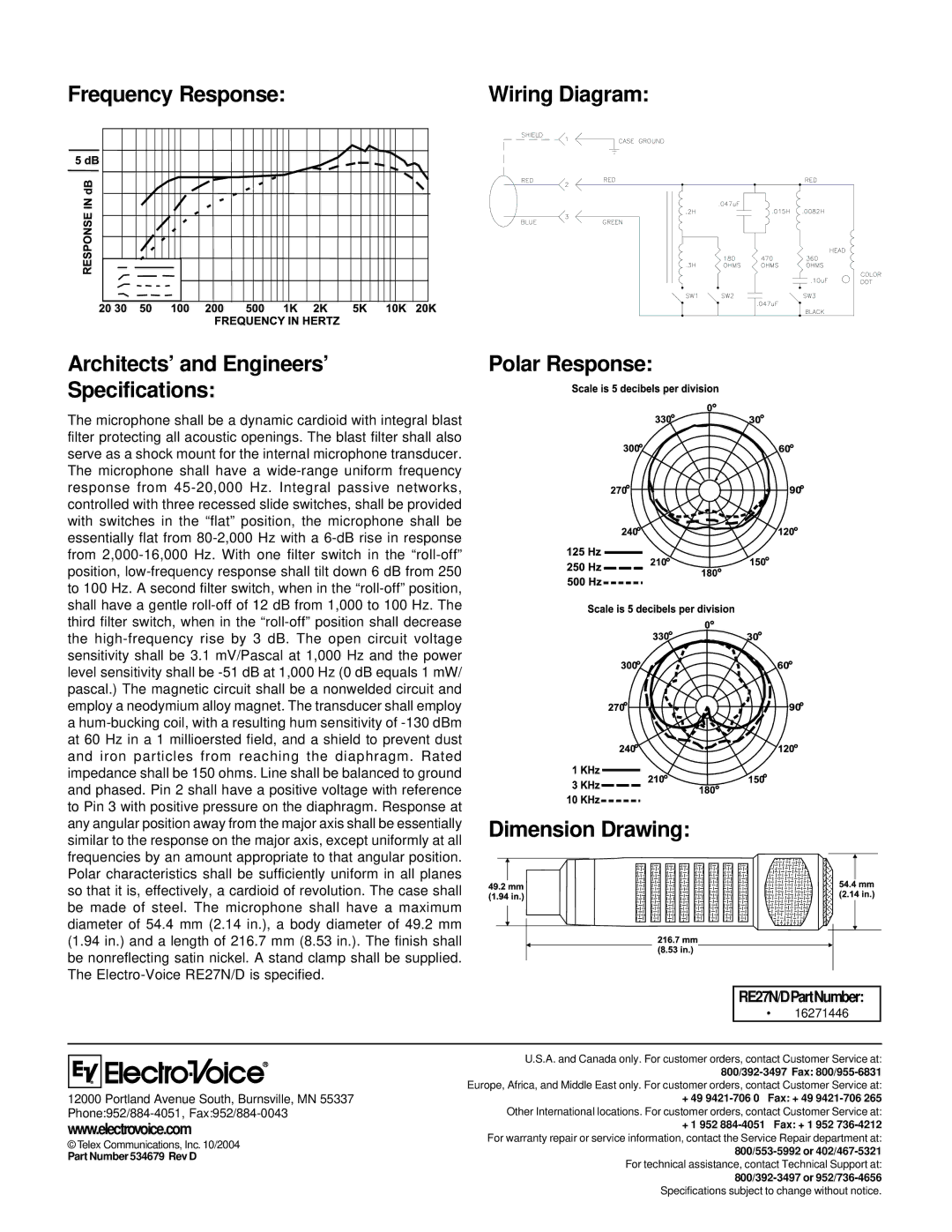
The microphone shall be a dynamic cardioid with integral blast filter protecting all acoustic openings. The blast filter shall also serve as a shock mount for the internal microphone transducer. The microphone shall have a wide-range uniform frequency response from 45-20,000 Hz. Integral passive networks, controlled with three recessed slide switches, shall be provided with switches in the “flat” position, the microphone shall be essentially flat from 80-2,000 Hz with a 6-dB rise in response from 2,000-16,000 Hz. With one filter switch in the “roll-off” position, low-frequency response shall tilt down 6 dB from 250 to 100 Hz. A second filter switch, when in the “roll-off” position, shall have a gentle roll-off of 12 dB from 1,000 to 100 Hz. The third filter switch, when in the “roll-off” position shall decrease the high-frequency rise by 3 dB. The open circuit voltage sensitivity shall be 3.1 mV/Pascal at 1,000 Hz and the power level sensitivity shall be -51 dB at 1,000 Hz (0 dB equals 1 mW/ pascal.) The magnetic circuit shall be a nonwelded circuit and employ a neodymium alloy magnet. The transducer shall employ
ahum-bucking coil, with a resulting hum sensitivity of -130 dBm at 60 Hz in a 1 millioersted field, and a shield to prevent dust and iron particles from reaching the diaphragm. Rated impedance shall be 150 ohms. Line shall be balanced to ground and phased. Pin 2 shall have a positive voltage with reference to Pin 3 with positive pressure on the diaphragm. Response at any angular position away from the major axis shall be essentially similar to the response on the major axis, except uniformly at all frequencies by an amount appropriate to that angular position. Polar characteristics shall be sufficiently uniform in all planes so that it is, effectively, a cardioid of revolution. The case shall be made of steel. The microphone shall have a maximum diameter of 54.4 mm (2.14 in.), a body diameter of 49.2 mm (1.94 in.) and a length of 216.7 mm (8.53 in.). The finish shall be nonreflecting satin nickel. A stand clamp shall be supplied. The Electro-Voice RE27N/D is specified.