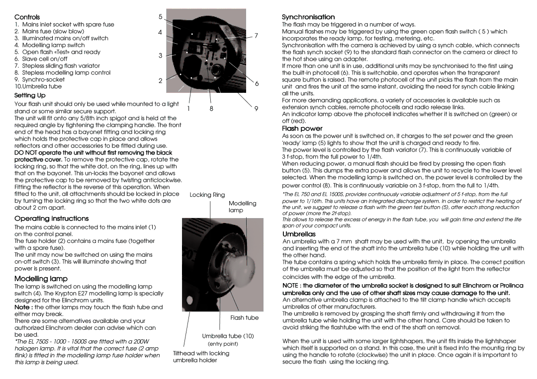
Controls | 5 | ||
1. | Mains inlet socket with spare fuse |
| |
2. | Mains fuse (slow blow) | 4 | |
3. | Illuminated mains on/off switch |
| |
4. | Modelling lamp switch |
| |
5. | Open flash «Test» and ready | 3 | |
6. | Slave cell on/off | ||
| |||
7. | Stepless sliding flash variator |
| |
8. | Stepless modelling lamp control |
| |
9. | 2 | ||
10.Umbrella tube
Setting Up
Your flash unit should only be used while mounted to a light stand or some similar secure support.
The unit will fit onto any 5/8th inch spigot and is held at the required angle by tightening the clamping handie. The front end of the head has a bayonet fitting and locking ring which holds the protective cap in place and allows reflectors and other accessories to be fitted during use.
DO NOT operate the unit without first removing the black protective cover. To remove the protective cap, rotate the locking ring, so that the white dot, on the ring, lines up with that on the bayonet. This
Operating instructions
The mains cable is connected to the mains inlet (1) on the control panel.
The fuse holder (2) contains a mains fuse (together with a spare fuse).
The unit may now be switched on using the mains
7
6
1 | 8 | 9 |
Locking Ring
Modelling lamp
Synchronisation
The flash may be triggered in a number of ways.
Manual flashes may be triggered by using the green open flash switch ( 5 ) which incorporates the ready lamp, for testing, metering, etc.
Synchronisation with the camera is achieved by using a synch cable, which connects the flash synch socket (9) to the standard flash connector on the camera or direct to the hot shoe using an adapter.
If more than one unit is in use, additional units may be synchronised to the first using the
For more demanding applications, a variety of accessories is available such as extension synch cables, remote photocells and radio release links.
An indicator lamp above the photocell indicates whether it is switched on (green) or off (red).
Flash power
As soon as the power unit is switched on, it charges to the set power and the green 'ready' lamp (5) lights to show that the unit is charged and ready to fire.
The power level is controlled by the flash variator (7). This is continuously variable of 3
When reducing power, a manual flash should be fired by pressing the open flash button (5). This dumps the extra power and allows the unit to recycle to the lower level selected. When the modelling lamp is switched on, the power level is controlled by the power control (8). This is continuously variable on 3
*The EL 750 and EL 1500S, provides continuously variable adjustment of 5
This allows to release the excess of energy in the flash tube, you will gain time and extend the life span of your compact units.
Umbrellas
An umbrella with a 7 mm shaft may be used with the unit, by opening the umbrella and inserting the end of the shaft into the umbrella tube (10) while holding the unit with the other hand.
The tube contains a spring which holds the umbrella firmly in place. The correct position of the umbrella must be adjusted so that the position of the light from the reflector
Modelling lamp
The lamp is switched on using the modelling lamp switch (4). The Krypton E27 modelling lamp is specially designed for the Elinchrom units.
Note : the other lamps may touch the flash tube and either may break.
There are some alternatives available and your authorized Elinchrom dealer can advise which can be used.
*The EL 750S - 1000 - 1500S are fitted with a 200W halogen lamp. It is vital that the correct fuse (2 amp flink) is fitted in the modelling lamp fuse holder when this lamp is being used.
Flash tube
Umbrella tube (10)
(entry point)
Tilthead with locking umbrella holder
coincides with the edge of the umbrella.
NOTE : the diameter of the umbrella socket is designed to suit Elinchrom or Prolinca umbrellas only and the use of other shaft sizes may cause damage to the unit.
An alternative umbrella clamp is attached to the tilt clamp handle which accepts umbrellas of other manufacturers.
The umbrella is removed by grasping the shaft firmly and withdrawing it from the umbrella tube while holding the unit with the other hand. Care should be taken to avoid striking the flashtube with the end of the shaft on removal.
When the unit is used with some larger lightshapers, the unit fits inside the lightshaper which itself is supported on a stand. In this case, the unit is fixed into the mountig ring by using the handle to rotate (clockwise) the unit in place. Once again it is important to secure the flash using the locking ring.