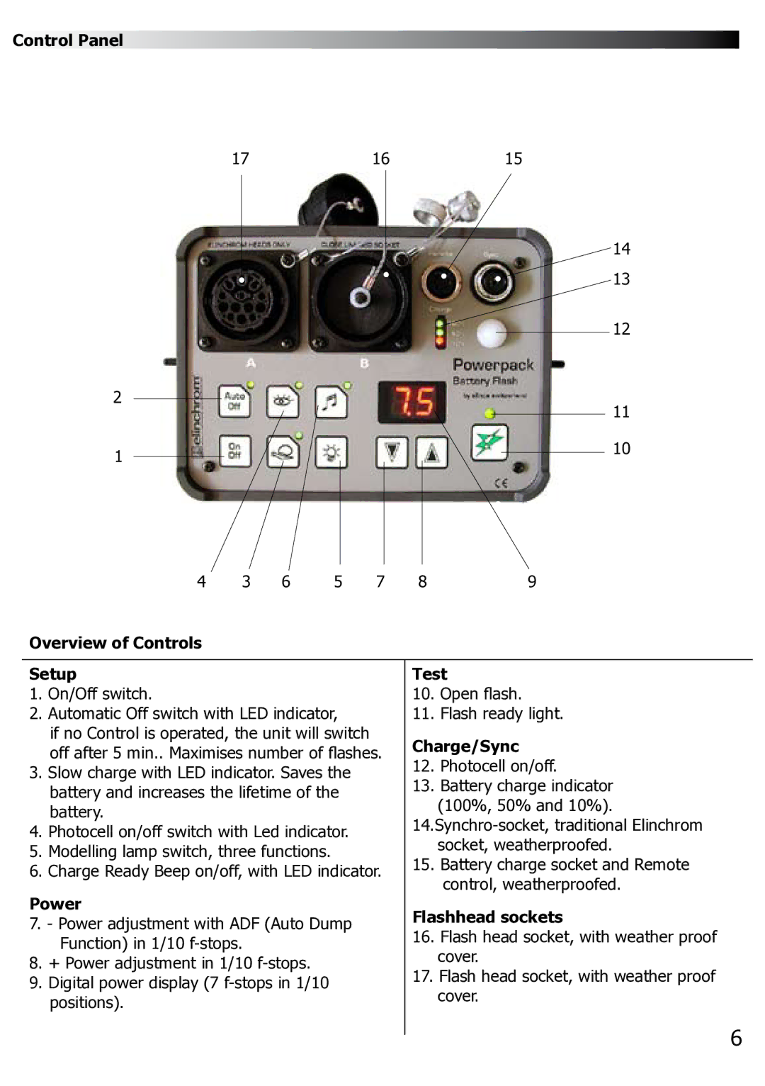
Control Panel
17 | 16 | 15 |
14
13
12
2 | 11 |
| |
1 | 10 |
|
4 | 3 | 6 | 5 | 7 | 8 | 9 |
Overview of Controls
Setup
1.On/Off switch.
2.Automatic Off switch with LED indicator,
if no Control is operated, the unit will switch off after 5 min.. Maximises number of flashes.
3.Slow charge with LED indicator. Saves the battery and increases the lifetime of the battery.
4.Photocell on/off switch with Led indicator.
5.Modelling lamp switch, three functions.
6.Charge Ready Beep on/off, with LED indicator.
Power
7.- Power adjustment with ADF (Auto Dump Function) in 1/10
8.+ Power adjustment in 1/10
9.Digital power display (7
Test
10.Open flash.
11.Flash ready light.
Charge/Sync
12.Photocell on/off.
13.Battery charge indicator (100%, 50% and 10%).
15.Battery charge socket and Remote control, weatherproofed.
Flashhead sockets
16.Flash head socket, with weather proof cover.
17.Flash head socket, with weather proof cover.
6