| PARTS LIST | |
|
|
|
ITEM NO. | PART NO. | DESCRIPTION |
|
|
|
1 | 23152C | BOX - INSULATION |
2 | 28070C | BASE ASSY |
3 | 27698C | PANEL |
4 | 28032C | PANEL - FRONT/REAR |
5 | 23158C | COVER - INSULATION BOX |
6 | 23159C | BRACKET - CONDUIT |
7 | 26701C | CABINET |
8 | 34783005 | WASHER - LOCK |
9 | 35882C | CONTROL - COLD |
10 | 66218C | CONDENSER ASSY |
11 | 31723000 | STRAINER |
12 | 30440C | CAPACITOR |
13 | 30768C | SOLENOID VALVE |
14 | 43242004 | CAPILLARY TUBE |
*15 | 48000036 | COMPRESSOR |
16 | 30248C | OVERLOAD |
17 | 48000070 | GASKET - TERM COVER |
18 | 48000067 | OVERLOAD SPRING |
19 | 48000069 | BALE STRAP |
20 | 48000068 | COVER - TERMINAL |
21 | 19037000 | CLIP - COMPRESSOR MTG |
22 | 100806740570 | GROMMET - COMPRESSOR MTG |
23 | 66216C | EVAPORATOR ASSY |
24 | 70772C | EVAPORATOR DRAIN PLUG |
25 | 31738002 | DRIER |
26 | 70020C | NUT |
|
|
|
*INCLUDES RELAY & OVERLOAD. IF UNDER WARRANTY REPLACE WITH SAME COMPRESSOR USED IN ORIGINALASSEMBLY.
NOTE: ALL CORRESPONDENCE PERTAINING TO ANY OF THE ABOVE WATER COOLERS OR ORDERS FOR REPAIR PARTS MUST INCLUDE MODEL NO. AND SERIAL NO. OF COOLER, NAME AND PART NO. OF REPLACEMENT PART.
NOTE: FOR USE WITH PHOTO PROCESSING APPLICATIONS, ADJUST THERMOSTAT TO WARMER SETTINGS.
HRC32W
START-UP
1.Open supply line valve.
2.Purge all air from all water lines by operating bubbler valve of fountain to which cooler is connected. A steady stream flow assures that all air is removed.
3.Rotate fan blade to assure proper clearance and free action.
4.Connect to proper electrical power.
IMPORTANT! INSTALLER PLEASE NOTE:
The grounding of electrical equipment such as telephone, computers, etc., to water lines is a common procedure. This grounding may be in the building, or may occur away from the building. This grounding can cause electrical feedback into a water chiller, creating an electrolysis which causes a metallic taste or an increase in the metal content of the water. This condition is avoidable by using the proper materials indicated below. Drain fittings which are provided by the installer should be plastic to electrically isolate the chiller from the building plumbing system.
TROUBLE SHOOTING & MAINTENANCE
Temperature Control: Factory set for 50°F water (± 5°) under normal conditions. For colder water, adjust screw on item no. 9 clockwise.
Ventilation: Cabinet louvers and condenser fins should be periodically cleaned with a brush, air hose, or vacuum cleaner. Excess dirt or poor ventilation can cause no cold water and compressor cycling on the overload protector.
Lubrication: Motors are lifetime lubricated.
Actuation of Quick Connect Water Fittings: Cooler is provided with
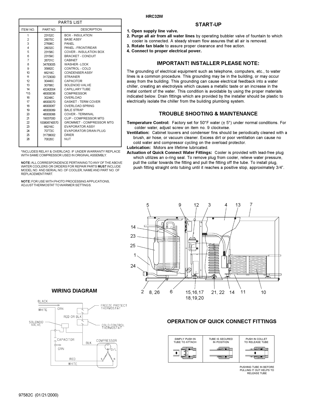
5 | 9 | 12 | 3 | 4 | 13 | 7 |
14
23
25
1
| 24 |
|
|
|
WIRING DIAGRAM | 2 8, 26 6 | 15,16,17 | 21, 22 14 11 | 10 |
|
| 18,19,20 |
|
|
OPERATION OF QUICK CONNECT FITTINGS
SIMPLY PUSH IN | TUBE IS SECURED | PUSH IN COLLET |
TUBE TO ATTACH | IN POSITION | TO RELEASE TUBE |
PUSHING TUBE IN BEFORE
PULLING IT OUT HELPS TO
RELEASE TUBE
97582C (01/21/2000)