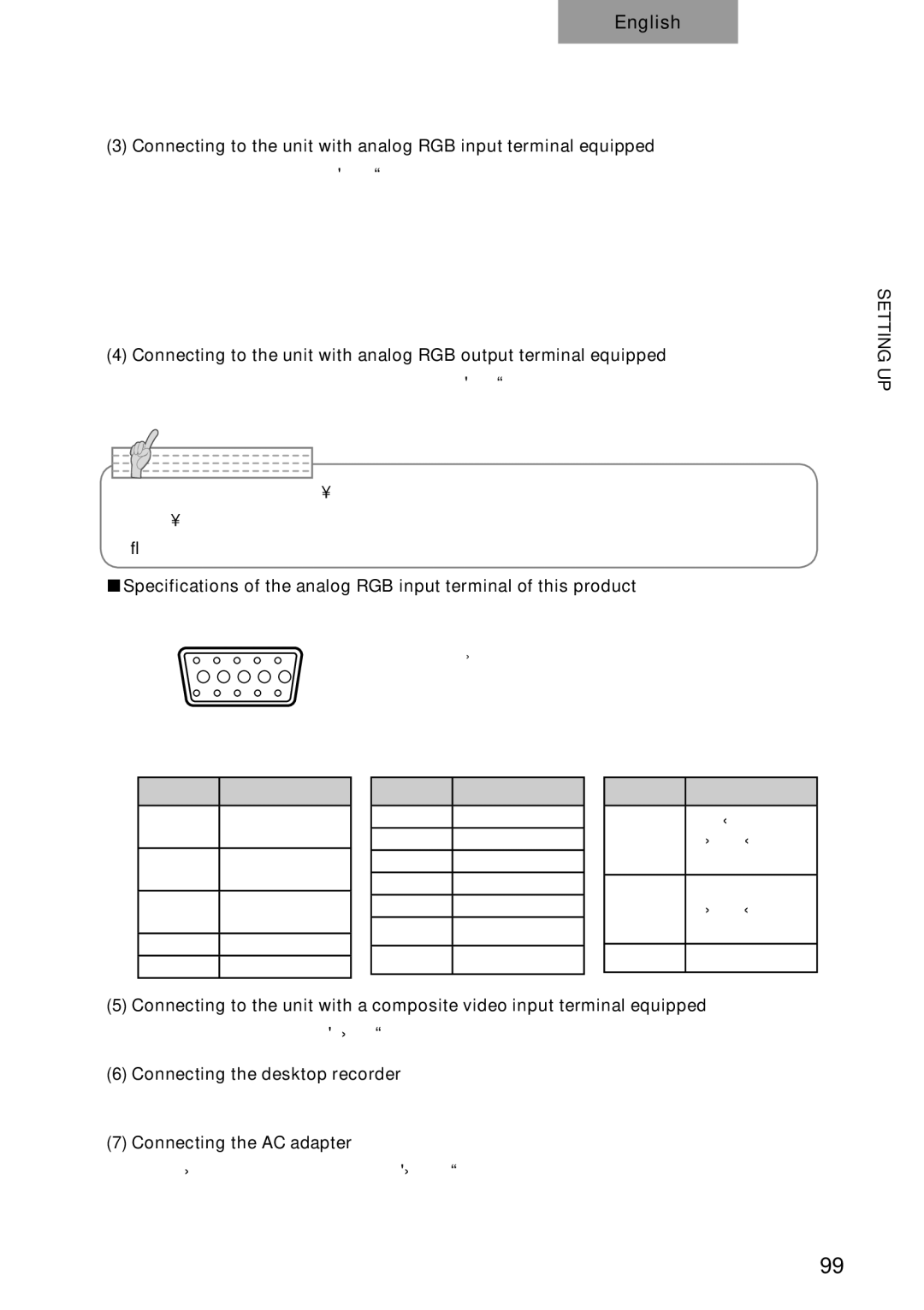
p10 specifications
The Elmo P10 is a cutting-edge document camera that has become highly regarded in educational and professional environments. Its design and functionality cater to a wide array of presentations, whether in classrooms, meetings, or seminars.A standout feature of the Elmo P10 is its high-resolution imaging capabilities. The camera boasts a resolution of up to 1080p, which provides crystal-clear images and video output. This clarity is essential for presenting detailed documents, illustrations, or real-time demonstrations without loss of quality. The P10 also features a 16x optical zoom, allowing users to focus on small details while maintaining sharp image quality.
One of the technological highlights of the Elmo P10 is its built-in LED light source. This lighting enhancement ensures that images remain visible and well-lit under various conditions, eliminating shadowing or glare that can distract from the presentation. The camera is also equipped with a versatile tilting arm, enabling users to position the camera at different angles easily. This flexibility is extremely useful for capturing 3D objects or large documents.
In terms of connectivity, the Elmo P10 offers a range of options, including USB and HDMI outputs. This versatility allows it to interface seamlessly with computers, projectors, and interactive whiteboards. The camera is compatible with various operating systems, making it an excellent choice for diverse technological setups.
Another feature that sets the Elmo P10 apart is its built-in image annotation capabilities. Users can draw or highlight directly on the image displayed on the screen, making it an interactive tool that enhances engagement in presentations. The P10 also includes a recording function that enables users to capture their sessions for later review or sharing, a significant advantage for educational settings or training programs.
The Elmo P10 is designed for portability, making it easy to transport between different locations. Its lightweight and compact design ensure that users can set up and dismantle quickly, minimizing downtime during presentations.
In summary, the Elmo P10 combines advanced imaging technology with user-friendly features, making it an invaluable tool for educators and professionals alike. With its high-resolution capabilities, versatile connectivity options, and built-in annotation tools, the Elmo P10 stands as a premier choice for anyone looking to elevate their presentation experience.

