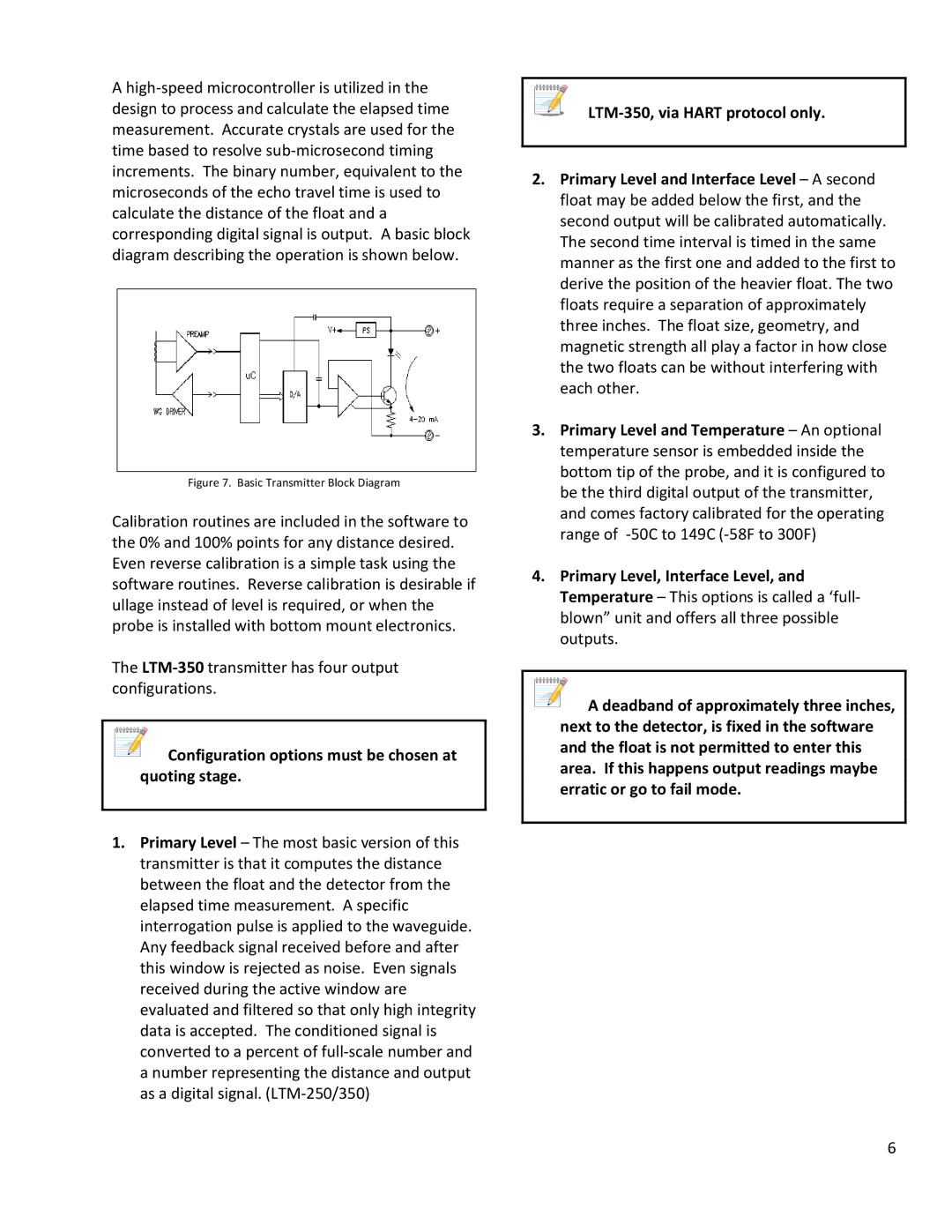
A high-speed microcontroller is utilized in the design to process and calculate the elapsed time measurement. Accurate crystals are used for the time based to resolve sub-microsecond timing increments. The binary number, equivalent to the microseconds of the echo travel time is used to calculate the distance of the float and a corresponding digital signal is output. A basic block diagram describing the operation is shown below.

Figure 7. Basic Transmitter Block Diagram

Calibration routines are included in the software to the 0% and 100% points for any distance desired. Even reverse calibration is a simple task using the software routines. Reverse calibration is desirable if ullage instead of level is required, or when the probe is installed with bottom mount electronics.

The LTM-350transmitter has four output configurations.

Configuration options must be chosen at quoting stage.

1.Primary Level – The most basic version of this transmitter is that it computes the distance between the float and the detector from the elapsed time measurement. A specific interrogation pulse is applied to the waveguide. Any feedback signal received before and after this window is rejected as noise. Even signals received during the active window are evaluated and filtered so that only high integrity data is accepted. The conditioned signal is converted to a percent of full-scale number and a number representing the distance and output as a digital signal. (LTM-250/350)

LTM-350, via HART protocol only.

2.Primary Level and Interface Level – A second float may be added below the first, and the second output will be calibrated automatically. The second time interval is timed in the same manner as the first one and added to the first to derive the position of the heavier float. The two floats require a separation of approximately three inches. The float size, geometry, and magnetic strength all play a factor in how close the two floats can be without interfering with each other.

3.Primary Level and Temperature – An optional temperature sensor is embedded inside the bottom tip of the probe, and it is configured to be the third digital output of the transmitter, and comes factory calibrated for the operating range of -50C to 149C (-58F to 300F)

4.Primary Level, Interface Level, and Temperature – This options is called a ‘full- blown” unit and offers all three possible outputs.

A deadband of approximately three inches, next to the detector, is fixed in the software and the float is not permitted to enter this area. If this happens output readings maybe erratic or go to fail mode.

6

Page 9
Image 9
Emerson 350, 250 operation manual Configuration options must be chosen at quoting stage, Basic Transmitter Block Diagram

350, 250 specifications

Emerson 250 and 350 are cutting-edge products that represent a significant leap in automation technology and process control systems. Designed with a focus on versatility, reliability, and efficiency, these systems are tailored to meet the demands of various industries, including manufacturing, oil and gas, and chemical processing.

One of the standout features of the Emerson 250 and 350 is their advanced control algorithms. These algorithms enable precise control of processes, allowing for enhanced stability and improved operational efficiency. By optimizing real-time decision-making, the systems can adapt to variable operating conditions, thereby reducing downtime and enhancing productivity.

The Emerson 250 and 350 are equipped with intuitive user interfaces that streamline operation and monitoring. These interfaces provide operators with easy access to critical data and insights, facilitating informed decision-making. The systems’ graphical displays and touch-screen capabilities enhance user experience, making it easier to configure settings and respond to alerts promptly.

Moreover, both models are built with robust communication protocols, ensuring seamless integration with existing infrastructure. This adaptability enables businesses to leverage their current investments in technology while expanding their automation capabilities. The systems support various communication standards, including OPC, Ethernet/IP, and Modbus, ensuring they can connect effortlessly to other devices and databases.

Another key characteristic of the Emerson 250 and 350 is their scalability. Designed to grow alongside a business, these systems can be expanded or modified to accommodate increasing operational demands. This flexibility is critical in today's fast-paced industrial environment, where agility and responsiveness are paramount.

In terms of reliability, the Emerson 250 and 350 boast rugged designs that withstand the harsh conditions often present in industrial settings. With features like enhanced environmental resistance and fail-safe mechanisms, these systems ensure continuous operation and minimize the risk of failures, providing peace of mind for operators.

In summary, the Emerson 250 and 350 stand out with their advanced control algorithms, user-friendly interfaces, robust communication capabilities, scalability, and reliability. These characteristics make them ideal solutions for businesses aiming to improve automation and process control while adapting to the ever-evolving demands of the industrial sector.