Site Planning Data, Liebert FS Flywheel Energy Storage System: 190 kW, 10 Seconds


Recharge


Discharge


Rotational Speed

Mechanical Data


Nominal Energy

Max. Current

Nom. Voltage

Nom. Power

Duration


Nom. Voltage

Min.

Max.

Dimensions

Weight

Losses

Storage

ADC

VDC

kW

seconds


VDC

rpm

rpm

W x D x H, in. (mm)

lb. (kg)

(W)

1900 kW-seconds

50

520

190

10


510

25,000

55,500

25 x 32.5 x 71

1300 (590)

< 300


(635 x 826 x 1803)


See Notes for Table (below):

1, 11

2, 11

4

4


3, 11

Notes for Table

1.Recharge current shown is the maximum the Liebert FS can accept. This value is dependent on the UPS, typically limited to 15% of the UPS’s nominal full load DC current.

2.Recharge voltage is adjustable, 480 to 500VDC. 190kW requires >520VDC.

3.Discharge voltage is adjustable, 480 to 500VDC. 190kW requires >510VDC.

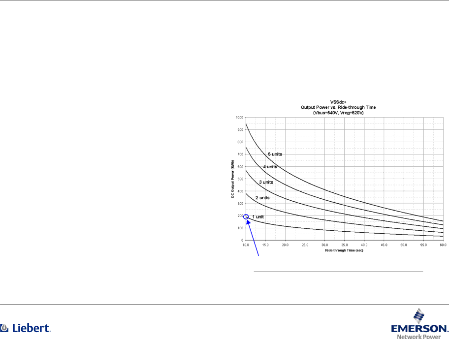
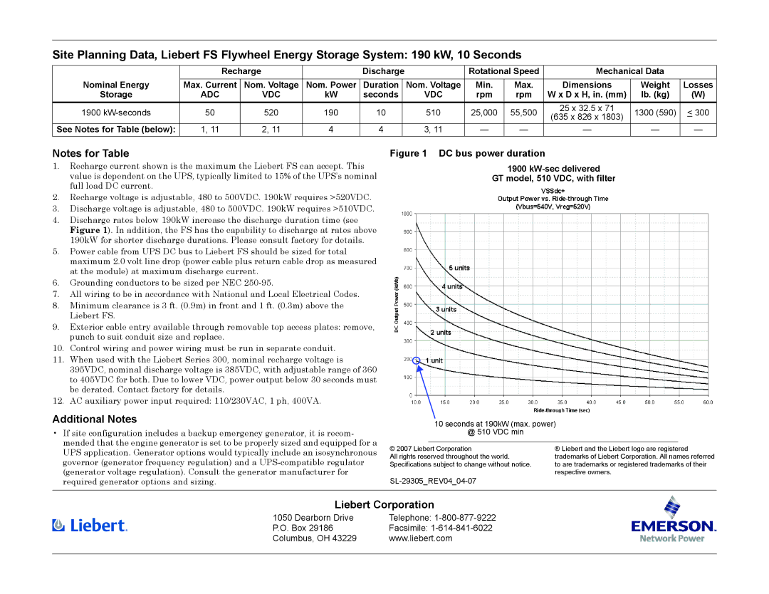
4.Discharge rates below 190kW increase the discharge duration time (see Figure 1). In addition, the FS has the capability to discharge at rates above 190kW for shorter discharge durations. Please consult factory for details.

5.Power cable from UPS DC bus to Liebert FS should be sized for total maximum 2.0 volt line drop (power cable plus return cable drop as measured at the module) at maximum discharge current.

6.Grounding conductors to be sized per NEC 250-95.

7.All wiring to be in accordance with National and Local Electrical Codes.

8.Minimum clearance is 3 ft. (0.9m) in front and 1 ft. (0.3m) above the Liebert FS.

9.Exterior cable entry available through removable top access plates: remove, punch to suit conduit size and replace.

10.Control wiring and power wiring must be run in separate conduit.

11.When used with the Liebert Series 300, nominal recharge voltage is 395VDC, nominal discharge voltage is 385VDC, with adjustable range of 360 to 405VDC for both. Due to lower VDC, power output below 30 seconds must be derated. Contact factory for details.

12.AC auxiliary power input required: 110/230VAC, 1 ph, 400VA.

Additional Notes

If site configuration includes a backup emergency generator, it is recom- mended that the engine generator is set to be properly sized and equipped for a UPS application. Generator options would typically include an isosynchronous governor (generator frequency regulation) and a UPS-compatible regulator (generator voltage regulation). Consult the generator manufacturer for required generator options and sizing.

Figure 1 DC bus power duration

1900 kW-sec delivered

GT model, 510 VDC, with filter

10 seconds at 190kW (max. power)

@ 510 VDC min

© 2007 Liebert Corporation

® Liebert and the Liebert logo are registered

All rights reserved throughout the world.

trademarks of Liebert Corporation. All names referred

Specifications subject to change without notice.

to are trademarks or registered trademarks of their


respective owners.

SL-29305_REV04_04-07

Liebert Corporation

1050 Dearborn Drive

Telephone: 1-800-877-9222

P.O. Box 29186

Facsimile: 1-614-841-6022

Columbus, OH 43229

www.liebert.com


Page 2
Image 2
Emerson 510 VDC specifications Additional Notes, Liebert Corporation, Adc Vdc

510 VDC specifications

The Emerson 510 VDC is a highly versatile and advanced digital control system designed for use in various industrial applications, particularly in the oil and gas, power generation, and process manufacturing sectors. This system exemplifies Emerson’s commitment to increasing efficiency, safety, and performance through innovative technologies and user-friendly features.

One of the main features of the Emerson 510 VDC is its ability to handle high voltage direct current (HVDC) applications. This is crucial for industries that require reliable energy transmission over long distances with minimal losses. The system supports advanced control algorithms that optimize the performance of HVDC links, ensuring stability and improved power quality.

The Emerson 510 VDC employs state-of-the-art digital signal processing technologies, which enable rapid response times and precise control of electrical systems. This allows for real-time monitoring and adjustments, ensuring that operations run smoothly and safely. With built-in redundancy features, the system enhances reliability, mitigating risks associated with equipment failures.

Another notable characteristic of the 510 VDC is its modular architecture. This enables users to easily configure and expand the system according to specific operational needs. Whether integrating new components or upgrading existing ones, the modular design simplifies maintenance and scalability, accommodating future growth without significant downtime.

Furthermore, the Emerson 510 VDC incorporates advanced communication protocols that facilitate seamless integration with other industrial systems and devices. This interoperability is critical for achieving a holistic view of operations and improving overall system performance. Additionally, the user interface is designed to be intuitive, providing operators with easy access to critical data and control mechanisms.

Safety is a prime consideration in the design of the Emerson 510 VDC. The system is equipped with comprehensive diagnostics and protective features that safeguard equipment and personnel. It adheres to strict industry standards, ensuring compliance and enhancing operational reliability.

In summary, the Emerson 510 VDC stands out for its advanced HVDC capabilities, high-performance digital processing, modular design, and enhanced safety features. These characteristics make it a vital component for industries looking to improve electric power efficiency, reliability, and management in an ever-evolving technological landscape. As industries continue to grapple with energy challenges, the Emerson 510 VDC offers a robust and flexible solution for modern energy demands.