4.The blade flanges have an interlocking feature that must be fully engaged before tightening the screw. Make sure all the flanges are properly engaged and then tighten the flange screws. If one of the flanges does not seat properly on the motor hub, loosen the adjacent flange screws,
REMOVE ONE M4 x 10mm
SERRATED PAN HEAD
SCREW AND LOOSEN THE
OTHER TWO SCREWS ![]()
![]()
ADAPTER PLATE
BLADE/FLANGE
ASSEMBLY
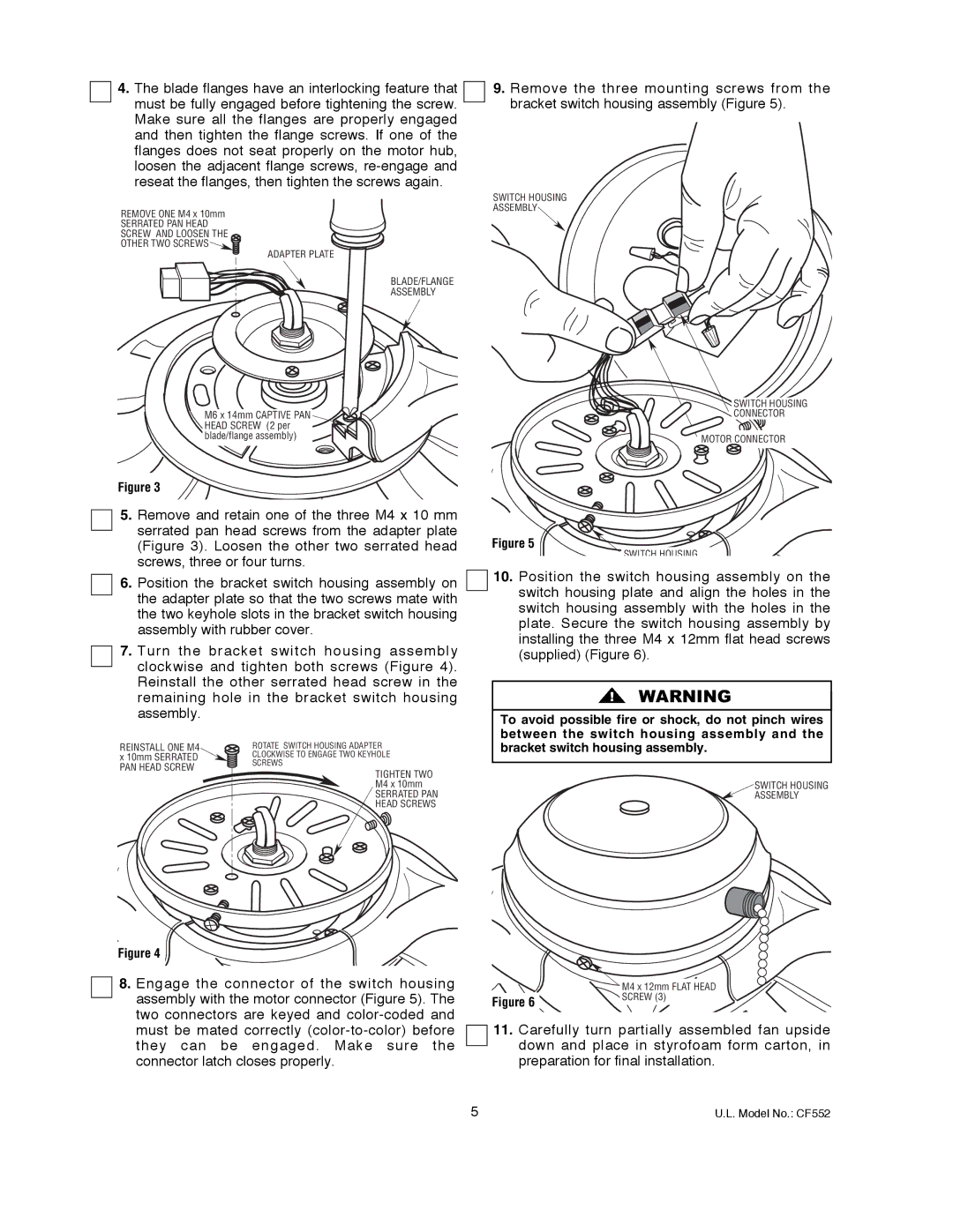
9.Remove the three mounting screws from the bracket switch housing assembly (Figure 5).
SWITCH HOUSING
ASSEMBLY
M6 x 14mm CAPTIVE PAN HEAD SCREW (2 per blade/flange assembly)
Figure 3
5.Remove and retain one of the three M4 x 10 mm serrated pan head screws from the adapter plate (Figure 3). Loosen the other two serrated head screws, three or four turns.
6.Position the bracket switch housing assembly on the adapter plate so that the two screws mate with the two keyhole slots in the bracket switch housing assembly with rubber cover.
7.Turn the bracket switch housing assembly clockwise and tighten both screws (Figure 4). Reinstall the other serrated head screw in the remaining hole in the bracket switch housing assembly.
REINSTALL ONE M4 | ROTATE SWITCH HOUSING ADAPTER | |
x 10mm SERRATED | CLOCKWISE TO ENGAGE TWO KEYHOLE | |
PAN HEAD SCREW | SCREWS | |
TIGHTEN TWO | ||
| ||
| M4 x 10mm | |
| SERRATED PAN | |
| HEAD SCREWS |
Figure 4
8.Engage the connector of the switch housing assembly with the motor connector (Figure 5). The two connectors are keyed and
SWITCH HOUSING
CONNECTOR
![]() MOTOR CONNECTOR
MOTOR CONNECTOR
Figure 5
SWITCH HOUSING
10.Position the switch housing assembly on the switch housing plate and align the holes in the switch housing assembly with the holes in the plate. Secure the switch housing assembly by installing the three M4 x 12mm flat head screws (supplied) (Figure 6).
!![]() WARNING
WARNING
To avoid possible fire or shock, do not pinch wires between the switch housing assembly and the bracket switch housing assembly.
SWITCH HOUSING
ASSEMBLY
| M4 x 12mm FLAT HEAD |
Figure 6 | SCREW (3) |
|
11.Carefully turn partially assembled fan upside down and place in styrofoam form carton, in preparation for final installation.
5 | U.L. Model No.: CF552 |