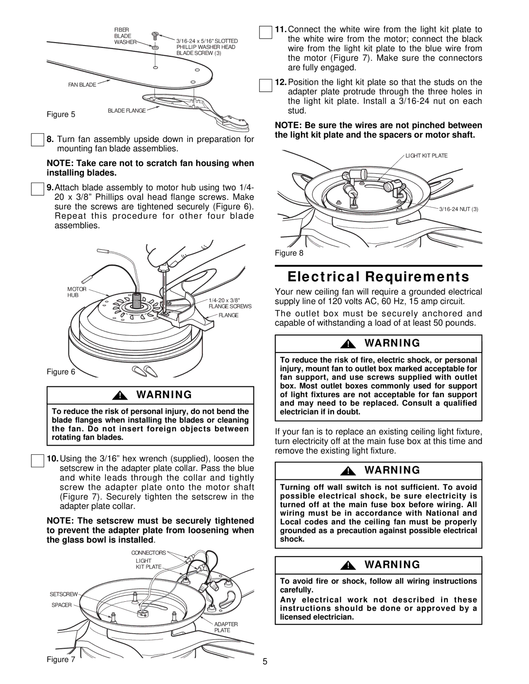
FAN BLADE
Figure 5
FIBER |
|
BLADE | |
WASHER | |
| PHILLIP WASHER HEAD |
| BLADE SCREW (3) |
BLADE FLANGE ![]()
![]()
11.Connect the white wire from the light kit plate to the white wire from the motor; connect the black wire from the light kit plate to the blue wire from the motor (Figure 7). Make sure the connectors are fully engaged.
12.Position the light kit plate so that the studs on the adapter plate protrude through the three holes in the light kit plate. Install a
NOTE: Be sure the wires are not pinched between the light kit plate and the spacers or motor shaft.
8.Turn fan assembly upside down in preparation for mounting fan blade assemblies.
NOTE: Take care not to scratch fan housing when installing blades.
9.Attach blade assembly to motor hub using two 1/4- 20 x 3/8” Phillips oval head flange screws. Make sure the screws are tightened securely (Figure 6). Repeat this procedure for other four blade assemblies.
MOTOR
HUB
FLANGE SCREWS ![]() FLANGE
FLANGE
Figure 6
!WARNING
To reduce the risk of personal injury, do not bend the blade flanges when installing the blades or cleaning the fan. Do not insert foreign objects between rotating fan blades.
10.Using the 3/16” hex wrench (supplied), loosen the setscrew in the adapter plate collar. Pass the blue and white leads through the collar and tightly screw the adapter plate onto the motor shaft (Figure 7). Securely tighten the setscrew in the adapter plate collar.
NOTE: The setscrew must be securely tightened to prevent the adapter plate from loosening when the glass bowl is installed.
CONNECTORS ![]()
LIGHT
KIT PLATE
SETSCREW
SPACER
![]() ADAPTER
ADAPTER
PLATE
LIGHT KIT PLATE
Figure 8
Electrical Requirements
Your new ceiling fan will require a grounded electrical supply line of 120 volts AC, 60 Hz, 15 amp circuit.
The outlet box must be securely anchored and capable of withstanding a load of at least 50 pounds.
!WARNING
To reduce the risk of fire, electric shock, or personal injury, mount fan to outlet box marked acceptable for fan support, and use screws supplied with outlet box. Most outlet boxes commonly used for support of light fixtures are not acceptable for fan support and may need to be replaced. Consult a qualified electrician if in doubt.
If your fan is to replace an existing ceiling light fixture, turn electricity off at the main fuse box at this time and remove the existing light fixture.
!WARNING
Turning off wall switch is not sufficient. To avoid possible electrical shock, be sure electricity is turned off at the main fuse box before wiring. All wiring must be in accordance with National and Local codes and the ceiling fan must be properly grounded as a precaution against possible electrical shock.
!WARNING
To avoid fire or shock, follow all wiring instructions carefully.
Any electrical work not described in these instructions should be done or approved by a licensed electrician.
Figure 7 | 5 |