
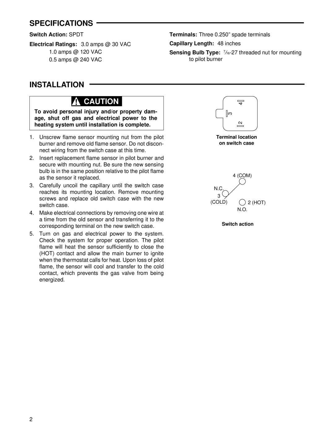
37-5392D specifications
Emerson Process Management 37-5392D is a powerful and versatile device that plays a significant role in various industrial applications. This particular model is part of Emerson's commitment to providing advanced solutions for process automation, contributing to increased efficiency and productivity in manufacturing and processing industries.One of the key features of the 37-5392D is its robust configuration options that allow for significant customization to meet specific operational requirements. The device supports a wide range of input signals and is compatible with various types of sensors, making it suitable for diverse environments. Its flexible architecture enables seamless integration with different automation systems, enhancing its utility in real-time process control.
The 37-5392D incorporates state-of-the-art technologies that elevate its performance. It typically employs advanced digital signal processing (DSP), which ensures high accuracy in measurement and data handling. This technology allows the device to maintain excellent stability under varying operational conditions, minimizing the risk of errors and boosting overall reliability.
Another notable characteristic of the 37-5392D is its user-friendly interface. The intuitive design streamlines setup and operation, enabling users to easily navigate through its functions and features. This aspect is particularly beneficial in reducing training time for operators, allowing them to become proficient in using the device much quicker.
Moreover, the device is equipped with diagnostic and predictive maintenance capabilities that help in anticipating issues before they escalate. This proactive approach to maintenance not only saves time and resources but also enhances the overall lifespan of the device, making it a cost-effective choice for industrial applications.
The 37-5392D is also designed with a focus on safety and compliance. It adheres to international standards and regulations, ensuring it meets the necessary safety protocols for industrial operation. This attribute makes it a reliable option for facilities striving to maintain high safety standards while optimizing their operational capabilities.
In summary, Emerson Process Management 37-5392D stands out in the realm of process automation with its customizable features, advanced digital technologies, user-friendly interface, and predictive maintenance capabilities. These attributes, combined with a strong emphasis on safety and compliance, position the 37-5392D as a vital tool for industries looking to enhance their automation and efficiency.