Manuals
/
Emotiva
/
Home Audio
/
Stereo Amplifier
Emotiva
UPA-5, UPA-1
manual
Front Panel Layout, Front Panel LED Display, Front Panel Power Switch
Models:
UPA-1
UPA-5
1
12
36
36
Download
36 pages
43.22 Kb
9
10
11
12
13
14
15
16
Troubleshooting
Specification
Install
Warranty
Safety Precautions
Front Panel Power Switch
Page 12
Image 12
Page 11
Page 13
Page 12
Image 12
Page 11
Page 13
Contents
Page
Page
SAFETY PRECAUTIONS
Troubleshooting Guide
TECHNICAL SPECIFICATIONS
Limited Warranty
Service Assistance
Safety Precautions
WIDE SLOT, FULLY INSERT
NEC National Electrical Code Standards
Antenna Grounding Outside the House
Thank You for your Purchase
Dan Laufman
Ultra Series Amplifiers Overview
UPA‐1
UPA‐2
UPA‐5 and UPA‐7
Ultra Series Amplifier Features
Power Rating Note ‘Peak’ vs. ‘Continuous’
Unpacking Your Ultra Amplifier
Inventory
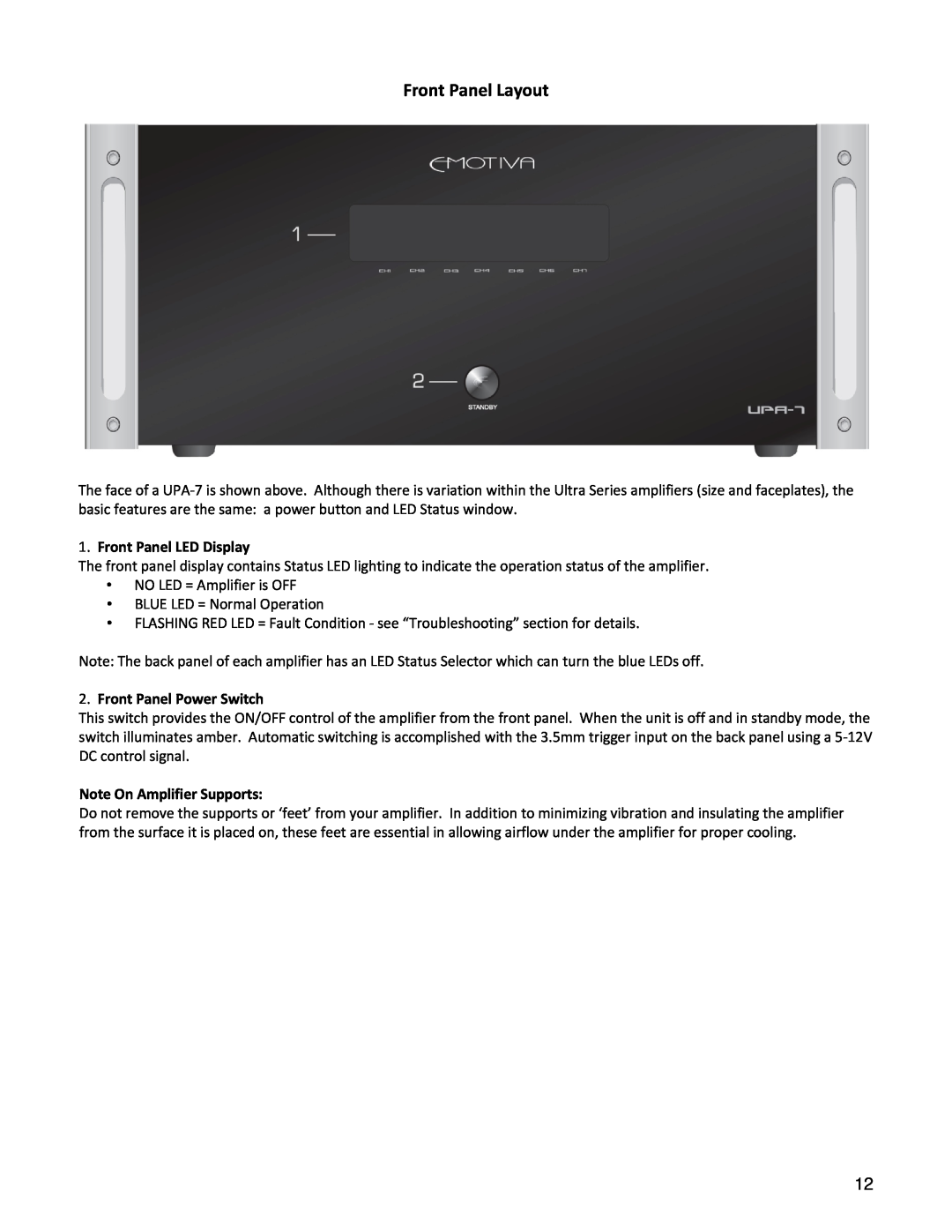
Front Panel Layout
2.Front Panel Power Switch
1.Front Panel LED Display
Note On Amplifier Supports
Back Panel Layouts UPA‐1 Back Panel
10.IEC Power Cable Connection
UPA‐2 Back Panel
10.IEC Power Cable Connection
UPA‐5 Back Panel
2.Channel Five Audio Input
3.Channel Four Audio Input
4.Channel Three Audio Input
14.IEC Power Cable Connection
9.Channel Five Speaker Terminals
10.Channel Four Speaker Terminals
11.Channel Three Speaker Terminals
UPA‐7 Back Panel
2.Channel Seven Audio Input
3.Channel Six Audio Input
4.Channel Five Audio Input
11.Channel Seven Speaker Terminals
Installation and Connections
AC Power Considerations
Physical Placement /Heat Considerations
Input Connection Considerations
Output Connection Considerations
Connection Tips for Superior Sound
Connection Diagram using a UPA‐7 for example
Page
Series and Parallel Speaker Connections
Series Connection
Parallel Connections
Technical Note about Multiple Speaker Connections
Troubleshooting Guide
Poor Bass Performance from Full Range Speakers
Turn‐on and Turn‐off Thumps
“Hum” Noises in the Speakers
A fault condition is one or more of the following
Problems with the whole A/V System
Other Probable Causes of Noise
TECHNICAL SPECIFICATIONS UPA‐1
UPA‐2
UPA‐5
UPA‐7
Limited Warranty
Service Assistance
Reference - Put you RMA number in this spot
Emotiva Disclosure
Top
Page
Image
Contents