Manuals
/
Emotiva
/
Home Audio
/
Stereo Amplifier
Emotiva
manual
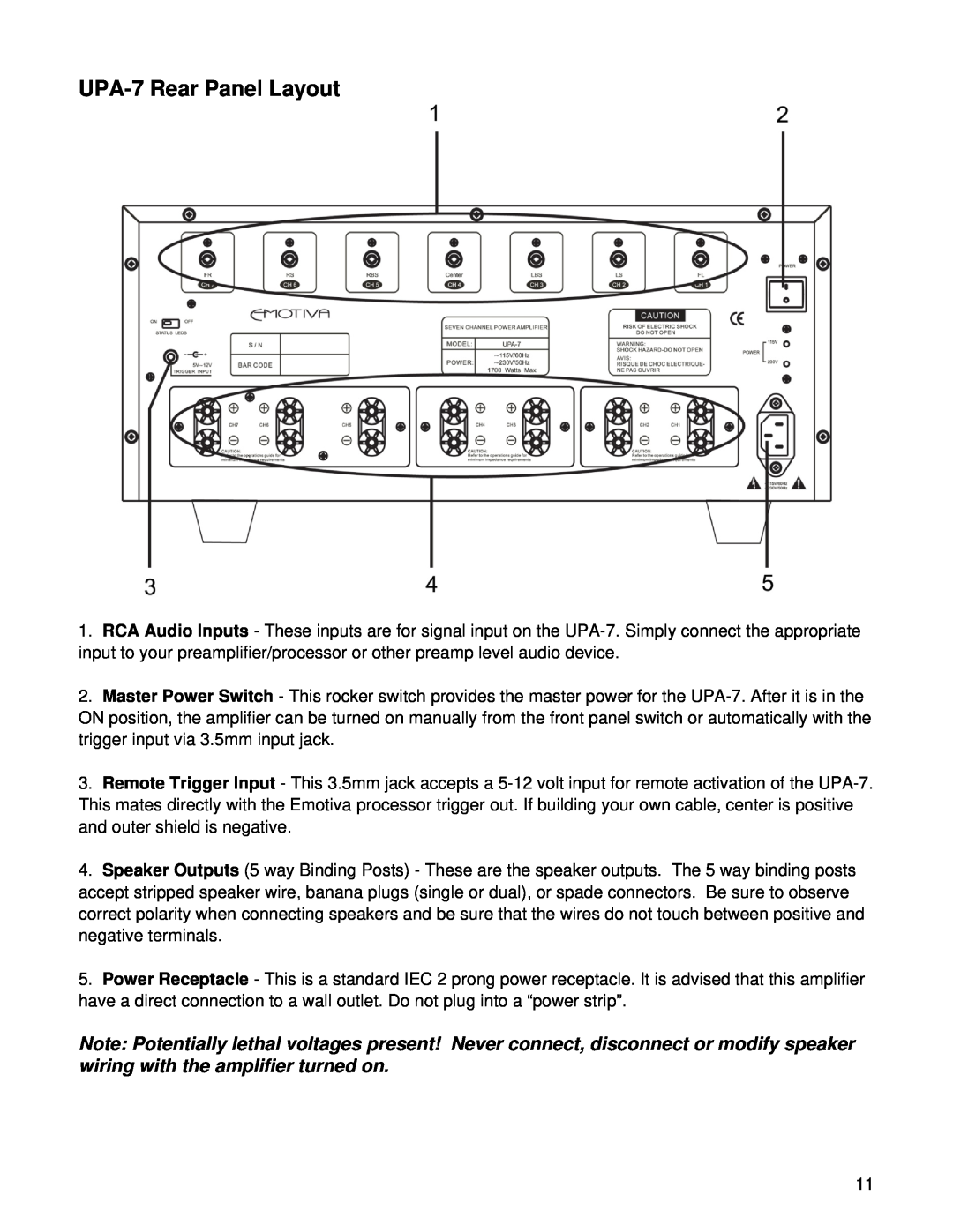
UPA-7Rear Panel Layout
Models:
UPA-7
1
11
27
27
Download
27 pages
57.16 Kb
8
9
10
11
12
13
14
15
Troubleshooting
Specifications
Install
Connection Diagrams
Warranty
Safety Precautions
Front Panel Power Switch
Page 11
Image 11
Page 10
Page 12
Page 11
Image 11
Page 10
Page 12
Contents
Page
Page
TABLE OF CONTENTS
Service Assistance for the UPA-7
Troubleshooting Guide
TECHNICAL SPECIFICATIONS
Limited Warranty
Safety Precautions
INTRODUIRE LA LAME LA PLUS LARGE DE L
DO NOT EXPOSE THIS APPLIANCE TO RAIN OR MOISTURE
OF PLUG TO WIDE SLOT, FULLY INSERT
ATTENTION POUR EVITER LES CHOCS ELECTRIQUES
NEC National Electrical Code Standards
Thank You for your UPA-7Purchase
Inventory
Emotiva UPA-7Seven Channel Amplifier Features
Unpacking the UPA-7
3.Rubber Feet
UPA-7Front Panel Layout
2.Front Panel Power Switch
1.Front Panel LED Display
UPA-7Rear Panel Layout
Physical Placement
Installation and Connections
AC Power Considerations
Connection Tips for Superior Sound
Input Connection Considerations
Output Connection Considerations
12V Trigger Connections
Connection using a 7 Channel Preamp/Processor
Connection Diagrams
Page
Series Connections
Series and Parallel Speaker Connections
Technical Note about Multiple Speaker Connections
Parallel Connections
Page
Troubleshooting Guide
“Hum” Noises in the Speakers
Turn-onand turn-offthumps
Other Probable Causes of Noise
Problems with the whole A/V System
A fault condition is one or more of the following
Input Impedance
TECHNICAL SPECIFICATIONS
Number of Channels
Amplifier Gain 30db
Service Assistance for the UPA-7
Limited Warranty
Copyright 2009 Emotiva
Emotiva Disclosure
Top
Page
Image
Contents