Manuals
/
Enterasys Networks
/
Computer Equipment
/
Switch
Enterasys Networks
BL-6000ENT
manual
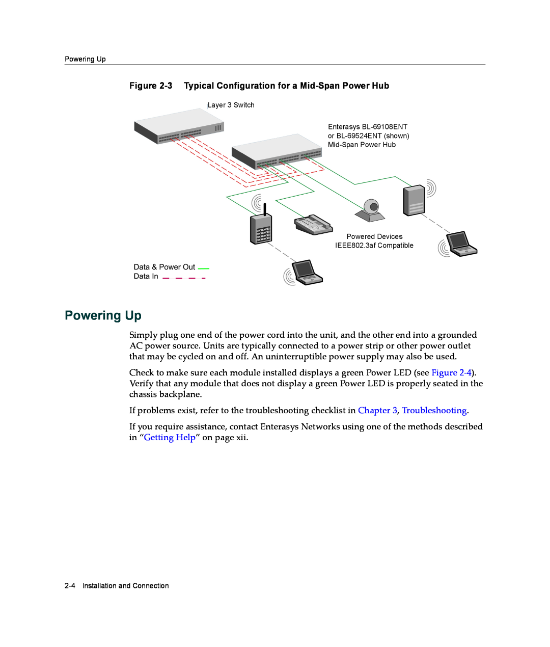
Powering Up, 3 Typical Configuration for a Mid-Span Power Hub
Models:
BL-6000ENT
1
22
30
30
Download
30 pages
39.53 Kb
19
20
21
22
23
24
25
26
Troubleshooting
Specs
Install
Port Indicators
Warranty
Safety
Powering Up
from Ethernet switch
Page 22
Image 22
Page 21
Page 23
Page 22
Image 22
Page 21
Page 23
Contents
User’s Guide
Mid-Span Power Hub 8-Port and 24-Port
7.5x9-inch cover with bleed on 4 sides
Page
Enterasys Networks, Inc 50 Minuteman Road Andover, MA
Federal Communications Commission FCC Notice
Product Safety
Regulatory Compliance Information
Industry Canada Notice
Elektro- magnetische Kompatibilität EMC
Electromagnetic Compatibility EMC
Compatibilidad Electromágnetica EMC
European Waste Electrical and Electronic Equipment WEEE Notice
VCCI Notice
BSMI EMC Statement - Taiwan
Manufacturer’s Name Enterasys Networks, Inc
ONE-YEAR LIMITED WARRANTY
Declaration of Conformity
Andover, MA USA
CAREFULLY READ THIS LICENSE AGREEMENT
Enterasys Networks, Inc Firmware License Agreement
BEFORE OPENING OR UTILIZING THE ENCLOSED PRODUCT
You and Enterasys agree as follows
3. APPLICABLE LAW. This Agreement shall be interpreted and governed under the laws and in the state and
9. OWNERSHIP. This is a license agreement and not an agreement for sale. You acknowledge and agree that the Program constitutes trade secrets and/or copyrighted material of Enterasys and/or its suppliers. You agree to implement reasonable security measures to protect such trade secrets and copyrighted material. All right, title and interest in and to the Program shall remain with Enterasys and/or its suppliers. All rights not specifically granted to You shall be reserved to Enterasys
Chapter 3 Troubleshooting
Contents
Chapter 2 Installation and Connection
Appendix A Hardware Specifications
Page
Purpose
About This Guide
Who Should Use This Guide
Your Enterasys Networks service contract number
Document Conventions
Getting Help
The following conventions are used in this guide
Network load and frame size at the time of trouble if known
xiv About This Guide
Port Indicators
Functions and Features
Introduction
Port Indicators
1-2 Introduction
Installation and Connection
Verifying the Kit
Figure 2-2 Contents of the BL-69524ENT Kit
Kit Contents
Figure 2-1 Contents of the BL-69108ENT Kit
Power Cord
Configuration for a Mid-Span Power Hub
Technical Considerations
Powering Up
Figure 2-3 Typical Configuration for a Mid-Span Power Hub
Detect / Power Forwarding Blue Power Green Data In
Figure 2-4 Module Bank for the 8-Port and 24-Port Mid-Span Power Hubs
Power / Data Out to device to be powered
from Ethernet switch
2-6 Installation and Connection
Problem
Troubleshooting
Table 3-1 Troubleshooting Checklist
Recommended Action
Table 3-1 Troubleshooting Checklist continued
Regulatory Compliance Standards
Hardware Specifications
Specifications
Product Standards
Table A-1 Physical and Mechanical Specifications
Physical/Mechanical Specifications
LED Indicators/Module
Model BL-69524ENT
Table A-3 Physical and Environmental Specifications
Physical/Environmental Specifications
Electrical Specifications
AC Power Input
Specifications
Top
Page
Image
Contents